The HP Memory Project Product Collection, Always Growing,
Becoming More and More Complete, with Significant Technical Additions
While building this collection, the guiding rule was - and is - to acquire the most technically significant products which best illustrate the influence they had on the evolution of measurement and computing technology over 60 years of the Hewlett Packard Industrial success story.
We are always looking for a new HP memoir to complete a product line history, or to illustrate the "HP Memories" of one or another HP old timer, remembering and writing his - or her - own experience about their career at HP.
Such a product search can last weeks, months or years for a specific item, as we scan EBay and other Internet sources. It often takes YEARS of waiting to find the desired product. Such a search was our recent acquisition of the HP 5060A Cesium Frequency Standard just below. Sometimes the search gives a surprising result with the apparition of an unexpected instrument, never published in any HP catalog. That was the case for the HP 400C, described lower in this page.
Nevertheless, one of our objectives, to populate the collection with one of each key product which was significant to the HP technology innovation history, came closer today.

It was the last "HP's World First" still missing in the collection
 |
HP 5060A World-First Transportable Cesium Beam Atomic Clock
HP Memory Project Collection |
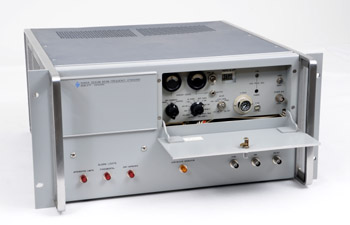
The HP 5060A,
The World's First Transportable
Cesium-Beam Atomic Clock
In 1963, an accurate primary time reference was only available in a few national physical laboratories. These national time and frequency standards used the cesium-beam resonator technology. In the U.S.A., the "NBS III" was the third generation cesium-beam resonator built at the National Bureau of Standards. Its proclaimed accuracy was +/- 6 parts in 10E12. The heart of this installation was the beam tube, a long cylinder, with an interaction length of 366 cm. The obvious limitation of those exceptional frequency standards was portability !
In 1964, HP technology allowed all the physical and electronic circuitry necessary to reproduce the functionalities of the NBS atomic clock to be enclosed into a single rack cabinet, with just a slightly lower specified accuracy of 2 parts in 10E11. The result was the HP 5060A, World First Transportable Cesium Beam Atomic Clock.
In his HP Memoir chapter titled "Our Finest Hour," the Cesium Atomic Clock, circa 1964, Alan Bagley, manager of the HP Time-Frequency Division during more than 25 years, recalls:
"That’s a takeoff on the Winston Churchill WWII pronouncement, but the technology which led HP to dominate the world of time keeping was based on our best product to that time, literally our finest and most accurate hour. By using the atomic resonance of the element Cesium, we created a time standard based on atomic physics, and not the resonance of a quartz crystal. This product was also in line with our stated product and business strategy of providing extremely precise RF signals.
Using this standard "Atomic Clock," our promotional department created a well-publicized world tour, which was dubbed the “Flying Clock.” The chair-sized instrument usually occupied a first class airline seat, with standby power supplied from the baby bottle warmer outlet in the galley. The idea was to visit global standards labs including our U.S. National Standard at the U.S. Naval Observatory in Washington, D.C. Then further comparisons were made at Swiss Observatory in Neuchatel. The clock was designed to maintain accuracy for 3000 years within only one second of error, a truly remarkable leap ahead for time keeping. Just in time for the Apollo Moon mission which required precise timing to carry out the critical navigation and communications.
The HP line of Cesium standards came to completely dominate the standards world, with most large and aerospace companies buying their own resident standard. And for decades, as the communications technology moved to digital formats, the transmitters and receivers were required to be synchronized to a very precise scale. This has become even more critical as the technology moved to fiber optics which exploit data rates in the 10 giga-bit region and higher."
Alan Bagley's HP Memories are published on this website. Click HERE
More information on the "Flying Clock" experiment in the July 1964 issue of the Hewlett Packard Journal, click HERE
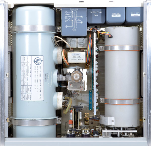 |
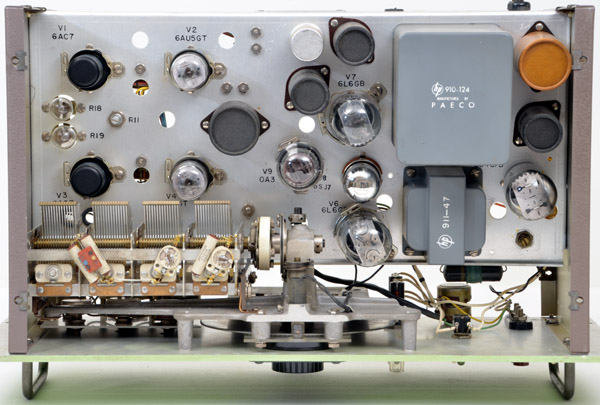
| The HP 5060A Inside layout, Top View |
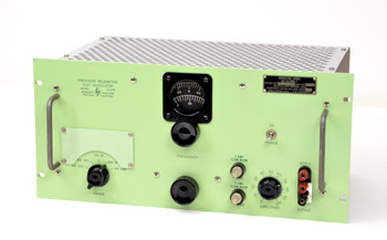 |
The HP 200TR
|
Another variation in the HP 200 Series, the Model 200T was designed for high stability applications. Introduced in the 1955 short-form catalog, and described in the April 1957 issue of the Hewlett Packard Journal, the HP 200T was especially convenient for high-resolution work such as encountered in the telemetering field. Data telemetry was used extensively in real-time aircraft and missile testing of the time. In flight tests, internal performance such as vibration, accelerations, orientation, and system operation were transmitted back to the ground control centers.
The HP 200T worst case stability was specified at 20 Hz per hour at a 100 kHz operating frequency after warmup and, of course, was generally noticeably better in a typical case. As a result, the instrument was especially suited to high-selectivity work such as checking the response of narrow-band filters, and testing frequency-selective amplifiers.
The200T frequency range extends from 250 Hz to 100 kHz, with wide overlap at both end of each range. The five ranges cover:
- 250 to 1000 Hz
- 800 to 3,200 Hz
- 2.5 to 10 kHz
- 8 to 32 kHz
- 25 to 100 kHz
The unusual color of this HP 200T in the HP Memory Project collection probably comes from a custom order of the US Signal Corps. Recently obtained on EBay, the unit is labeled SG-118/MRQ-7, military-type nomenclature. The rack-mount front panel has also an unusual thickness, about 5-times the thickness of a common series 200 instrument. Such thick and rigid front panels were often used for rack mounted instruments in mobile trailers to withstand rugged transport conditions. The left and right flanges of the cabinet are both in the HP standard grey paint color of that era. Another specific characteristic of this particular military ruggedized unit is that the bottom chassis wiring is tropicalized. See pictures below.
 |
| The HP 200T Inside, Top View |
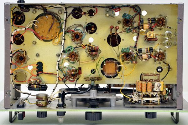 |
| The HP 200T Inside, Bottom View |
 |
Another HP 400C Electronic Voltmeter
in the HP Memory Project Collection |
The HP 400C in Another Cabinet Style
Collecting vintage instruments, as we do, often leads to surprises. One expects to see HP electronic voltmeters from the early years, before the introduction of standardized cabinets, to have sloping panels or narrow wrap-around bezel designs.
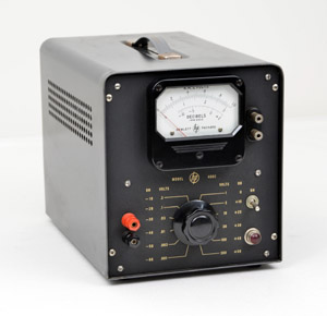
But it seems that the HP 400C was produced in several different cabinet styles and front panel layouts. This instrument, shown on the left, in our collection, not only has a different cabinet design, and wider configuration, but it is painted in black, very much unlike all similar years' offerings. Perhaps it was a custom job, for some customer lab that standardized on black.
The picture below shows, side by side, a HP 400A, and the recently acquired HP 400C. But this case style, different than the original inclined front panel, was never pictured in any HP catalog.
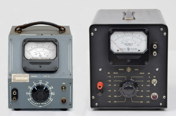 |
| Original production shape of the HP 400A and 400C on the left - A never-before seen HP 400C on the right |
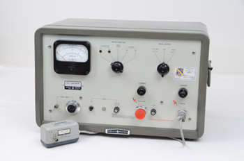 |
The HP 342A Noise Figure Meter and HP 343A VHF Noise Source
|
The HP 342A Noise Figure Meter
Hewlett-Packard's first microwave noise figure meter was the Model 340A, introduced in January, 1958. It featured 2 hard-wired IF frequency selections, 30 and 60 MHz. Fairly quickly, HP got customer feedback asking for other frequencies, because microwave systems were being designed for various reasons, with other higher IF circuitry.
Thus the HP 342A Noise Figure Meter was introduced a year later in the 1959 catalog, and described in the 1959 February-March issue of the Hewlett Packard Journal. Its main difference from the 340A was that it had 5 selectable IF input frequencies, 30, 60, 75, 105 and 200 MHz. Custom IF frequencies could be ordered with a modest handling cost.
In radio communications, or radar surveillance systems, the weakest signal that can be used is usually determined by the amount of noise added by the receiving system. This inherent noise of any receiving system is always resident at the very first stage, an rf preamplifier, or in the superheterodyne down-conversion stage at the front end. Once passed through that first stage, it doesn't do any good to add more amplification, because BOTH the desired signal and the receiver's added noise get amplified together, meaning the signal to noise ratio stays virtually the same.
Thus, any decrease in the amount of noise generated at the first stage in the receiving system will produce an increase in the output signal- to-noise ratio equivalent to a corresponding increase in received signal. From a performance standpoint, an increase in the signal-to-noise ratio by reducing the amount of noise in the receiver is more economical than increasing the received signal level by raising the power of the transmitter. For example, a 5 db improvement in receiver noise figure is equivalent to increasing the transmitter power by 3:l. It is clearly more economical to work on noise figure.
Hewlett-Packard Model 342A Noise Figure Meter measures noise figure as a function of the ratio between the noise output of the receiver under test, compared to a known amount of noise introduced at the input, and to the noise output when the device is terminated in its normal load. The noise input is supplied by a family of calibrated microwave noise sources, either argon or neon gas discharge tubes, or in the case of rf bands, a thermally-limited diode source.
Depending on the Noise Source connected to the HP 342A, the Noise Figure Measurement can be done from 10 MHz to 600 MHz in coaxial systems, and from 2.6 to 18 GHz in waveguide systems.
The HP 342A, at its introduction, was advertised as "A New Instrument Which Speeds Noise Figure Measurements,"
"Receiver and component alignment jobs that once took skilled engineers a full hour are now done in 5 minutes by a semi-skilled worker. Receiver noise figure can often be improved over the best adjustment previously possible. For instance, a 3 dB improvement in receiver noise figure equals doubling transmitter output. Since accurate alignment is easy, equipment is better maintained and peak performance enjoyed regularly."
A good proof of its performance and efficiency
was its 22-year lifetime in the HP general catalog. The Model 342A was still listed in the 1981 catalog.
The HP 342A was finally obsoleted by a brand new microprocessor-based instrument, the HP 8970A, in 1983, which featured measurements of both amplification and noise figure. This was a handy combination, because often in the design of the first stage of a microwave receiver, you are willing to trade off a loss of gain to achieve a lower noise figure.
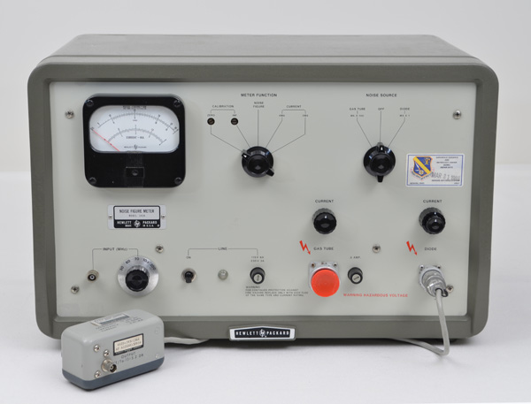 |
| Front Panel of the HP 342A Noise Figure Meter, shown with the HP 343A coaxial VHF noise source. |
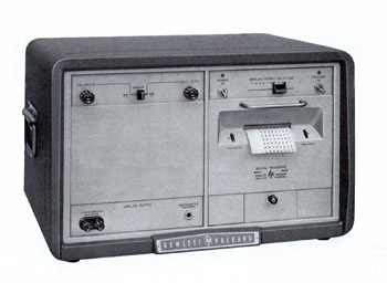 |
The HP 560A Digital Recorder |
The HP 560A,
Another HP's World First
This product was acquired to illustrate both Alan Bagley's HP Memories, and a chapter dedicated to Data Acquisition and Logging Instruments, in the Quick Tour on the website.
The first product line to be converted to digital at HP was the Electronic Counter line, designed and produced by the Frequency & Time Division. Consequently, it was the F&T Division which was the first to recognize a serious need for instruments which could record the data acquired and displayed by a Frequency Counter. . . No technician could write as fast as a digital counter could measure! Nor could a technician be available hour after hour for a test running for a long period.
The result of these considerations was the Model 560A Printer, introduced in 1956, and described in the March 1957 issue of the Hewlett Packard Journal. The immediate commercial success of this innovative instrument then generated a new series of slightly different models. They have different capabilities to accommodate the growing variety of instruments from which digital data could be recorded. The staircase voltage method of transferring data from the digital (NIXIE) displays seemed unusual, but cleverly required only a single wire per digit rather than 4-per-digit that were later used for BCD connections.
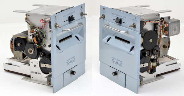 |
| Left and Right View of the HP 560A Digital Recorder/Printer Mechanism |

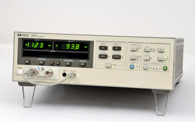 |
The HP 8508A Vector Voltmeter |
A Successor for the HP 8405A
When introduced in 1966, the HP 8405A Vector Voltmeter was not only an innovative new type of measuring instrument, it was also the introduction to a new way to characterize the amplitude and phase of an RF signal in the form of "Vector Measurement." And above all, this new 1000 MHz tool revitalized an old standard for the characterization of RF components: The "S" Parameters.
The 8405A was such a successful instrument that it had a 22-year lifetime in the HP general catalog, up to the 1988 edition. It was replaced in 1989 by a fully digital, and programmable version, the HP 8508A, shown on the right.
As usual at HP, when a completely new technology was introduced, the main concern was: 1) To produce the best possible instrument, making available all the innovation of this technology to the customer. And 2) To publish all the necessary tutorial and application documents which will help the customer to become comfortable in using this new technology. This rule of thumb was particularly true at the introduction of the HP 8405A Vector Voltmeter; a never-seen-before technology. The Application Notes below were all dedicated to an in-depth knowledge base of the HP 8405A possibilities; and these basics directly apply to the 8508A as well:
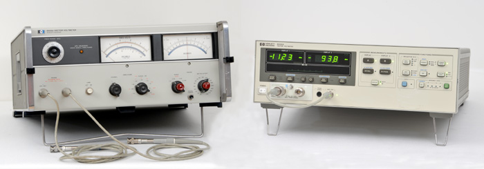 |
| The HP 8405A on the left, and its successor, the HP 8508A on the right |
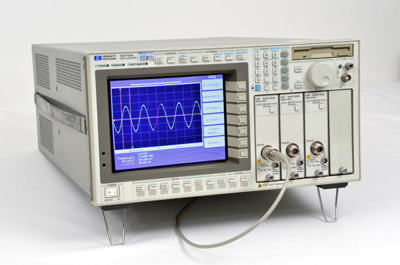 |
The HP 54710A |
The HP 54710A,
Digitizing Oscilloscope
The 1980-1990 decade was a transition period for HP oscilloscopes. It would take those 10 years, to completely change the concept and design of an oscilloscope. There would not be any more pure-Analog Oscilloscopes produced after 1983. The nascent "Digitizing" technology (ADC) was not yet fast enough to compete with the 100 MHz analog bandwidth, which was then considered as a major characteristic for a serious laboratory grade oscilloscope. As the Analog to Digital Converters (ADC) design strategies advanced, this gave birth to a new generation of instruments called "Digitizing Waveform Recorders." Starting with the HP 5180A, a 20 MHz, 2 Channel, 10 bit ADC resolution, introduced in 1983, it would still take another 5 years of ADC technology evolution to raise the performance of Digitizing Waveform Recorders into the 250 Megasamples per second range.
With four more creative years of digitizing technology evolution, (sampler circuits, analog-to-digital converters, and digital memories) all the benefits of the Digitizing Waveform Recorders were ready to be integrated into a general purpose Digitizing Oscilloscope. For the first time, in 1992, with the HP 54600, it was possible to advertise an oscilloscope with this significant slogan "The Feel of Analog, the Power of Digital."
One of the most sophisticated oscilloscopes produced by Hewlett Packard during the 1990s, before the HP/Agilent split, was the 54700 series. For the opening of the last archive period of the quick tour, 1980-2000, with a chapter dedicated to "Oscilloscope, Digitizer & TDR," it was a good opportunity to add one member of the 54700 series to the collection.
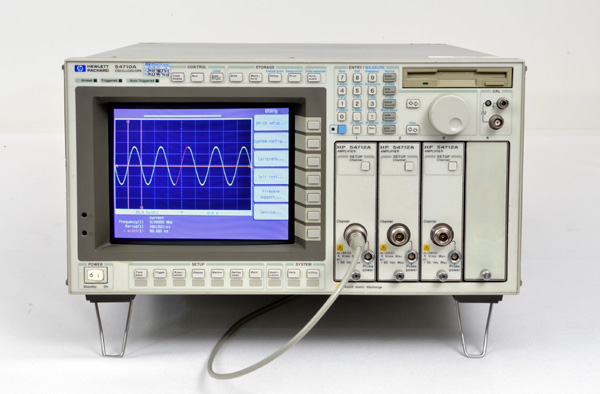 |
| The HP 54710A, if measurement power = number of pushbuttons, this scope is a performance winner. |
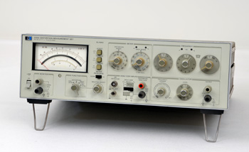 |
The HP 339A Distortion Measurement Set |
The Last Analog Distortion Meter, HP 339A
Audio frequency distortion measurement was a very early concern at HP, from the days when Bill Hewlett himself was designing audio products. One consequence of the first HP products, which were mostly audio oscillators operating in the low frequency range, was that the designers needed a tool to quantify their signal distortion. As soon as 1945, a vacuum tube distortion meter, the HP 330B was introduced for solving most problems of signal distortion measurement.
Twenty years later, in 1965, it was time to update the distortion meter product line with fully transistorized instruments. A complete family of four new instruments was introduced, and described in the April 1966 issue of the Hewlett Packard Journal. The four new analyzers all use the same measuring circuitry with wide filter tuning range, from 5 Hz to 600 kHz, and broad voltmeter frequency range, up to 3 MHz.
In this new family, for applications where lower initial cost was more important than speed and convenience of automatic nulling, Models 331A and 332A, had precision mechanical drives for accurate manual tuning without automatic nulling. For a little higher price, both Models HP 333A, and HP 334A, included an automatic nulling circuitry.
Even after the introduction of the 339A in 1978, most of the models of the HP 33X family would stay available in the general catalog until the beginning of the 1980s... Another 20-year lifetime family in the Hewlett Packard production.
Still an analog instrument, the HP 339A introduced in 1978, featured more advances in its technical specifications. The Model 339A Distortion Measurement Set is an ultra low distortion measuring system, complete with Total Harmonic Distortion (THD) Analyzer, true-rms voltmeter, and built-in, ultra low distortion tracking sine-wave oscillator. The instrument allows THD distortion measurement as low as 0.0018% over a 10 Hz to 110 kHz frequency band including harmonics to 330 kHz.
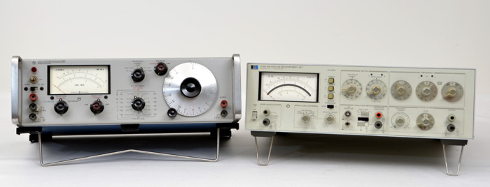 |
| The HP 332A on the left, and its successor, the HP 339A on the right |