
The Mechanical Complexity of Klystron Signal Generators
The accuracy, stability, and repeatability of the microwave generators of this time period, all depended crucially on the quality of their mechanical design and construction. Another story, previously published on this website clearly illustrates how the quality of electronics of this era relies on the creativity of the mechanical engineer assigned to the project. The Memories of Edward Phillips describe a number of innovative techniques and tools developed by the HP machine shop to achieve the best performance of all of the Klystron generators during the 1950s and 1960s decades.
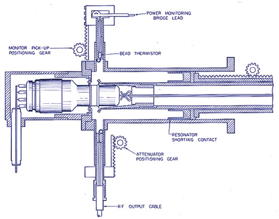
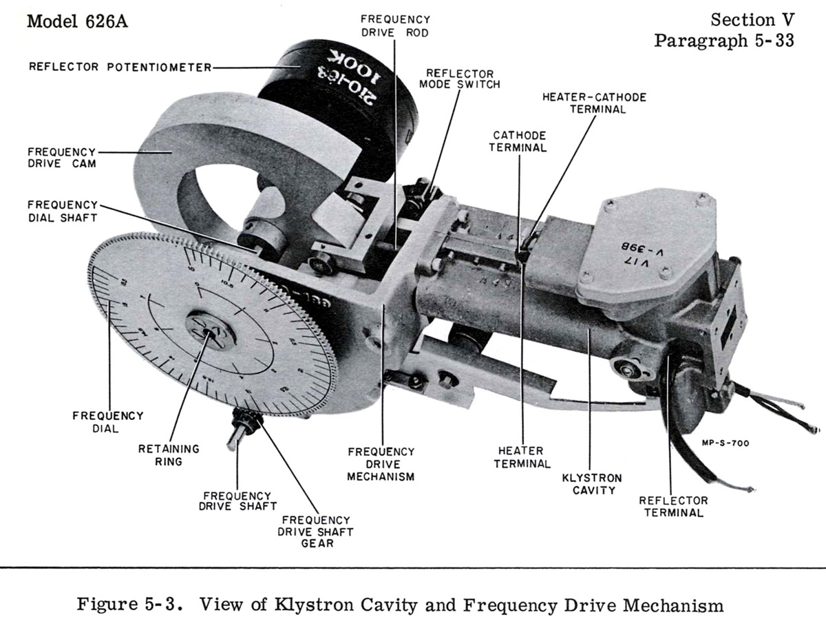
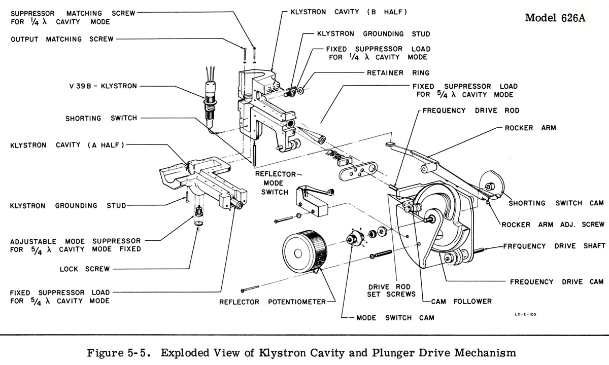
Mechanical connections to the front panel controls first involved tuning the cavity plunger, and usually required a non-linear mechanism. The 626 cavity shown below used a cam drive to match the Klystron tuning curve. The 618 cavity is not shown, but it used a "scissors-type" mechanism. These solutions required not just extreme precision, but zero-backlash arrangements. Inside the coaxial cavity, the metal-to-metal, sliding, shorting fingers had to operate for years, without scoring the surfaces, and yet not develop debris which would cause bad electronic effects like signal noise. HP's skill at mechanical lapping techniques were largely responsible for this high performance.
Two other front panel knobs controlled the power MONITORING probe, which interacted with the power OUTPUT probe, to make a convenient single dial and cursor on the panel. These connections also had to show ZERO backlash.
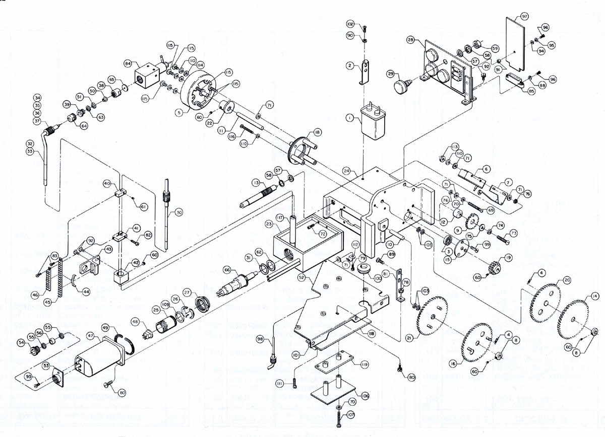
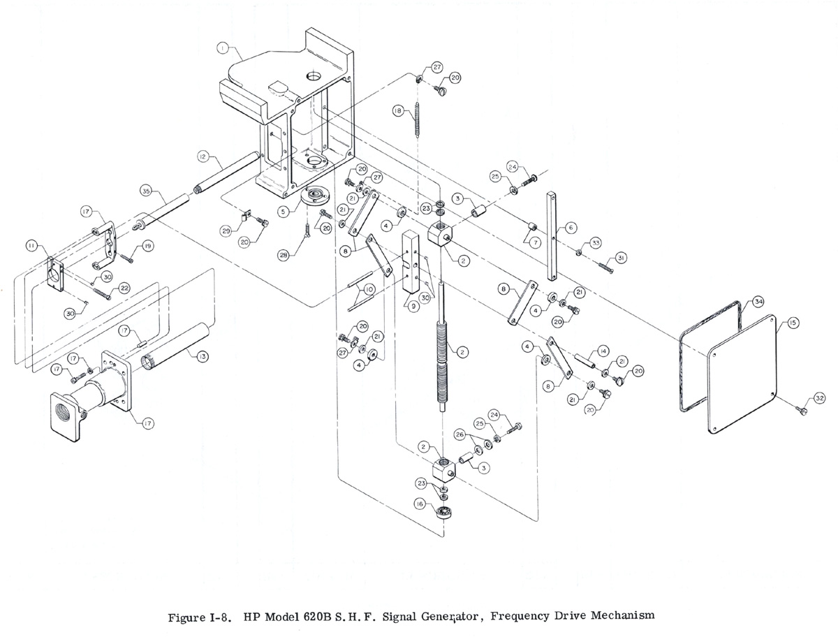
The pictures below show the simplified internal diagrams and mechanical designs of several Klystron cavity oscillators, common to most UHF and microwave generators of that era.
So even if the front panel appearance of these generators seem to indicate that they had all the same internal design, as Art told us in his memories, this was not true. As a function of the frequency range to be covered, dealing with dimensions of the cavity, and Klystron mode of oscillation, the engineers would produce very different designs, as required by those infuriating Klystron tubes.