HP Memories


I joined the HP Microwave lab on February 3, 1969. The time I spent in Microwave continued on for 21 years. Then on about 3/27/90 I retired and left the Microwave Division (at that time called Stanford Park Division) and came back the next day as a contract employee and consultant doing the same thing I did before retirement. Why? We'll discuss that in a later segment of these chapters. Since my involvement in Microwave covered so many years I'm going to break this up into 3 segments.
On 2/3/69, I was assigned to Brian Unter's Spectrum Analyzer section. Brian and his team just completed the development and introduction into production of the 8552A IF (Intermediate Frequency) section and the 8553L RF (Radio Frequency) section of a spectrum analyzer that plugs into a 140S Oscilloscope mainframe. The whole system was part of a family of spectrum analyzers that were smaller, more convenient to use, broader range and more accurate than our previous model and the competition. The 140S mainframe was a modified 140A, developed in the oscilloscope lab a few months earlier. Its panel was re-designed by Jack Magri, a fine and competent Industrial Designer. His design was to compliment this new family of spectrum analyzers and plug-ins.
My first assignment by Brian was to improve on the range of the intensity control of the 140S. It was just too coarse. A few degrees of rotation of the control would go from nearly off to full brightness. Because of my earlier experience in the scope lab this was an easy assignment. I changed the control from a linear taper to a logarithmic taper and solved the problem. It was easily done in one afternoon. That worked well. . . problem solved. . . what's next? Brian was impressed that the solution was so fast and simple.
These next couple of paragraphs make one wonder if we know what we are doing. It wasn't at all typical of this microwave group. As a new guy on the block, I wasn't involved in any decision making. . . I just did what Brian told me to do. I've often wondered why the RF plug-in was initially called an 8553L, then we changed it to 8553A, then we changed it to a 8553B. I'm sure Brian told me but I've forgotten. Maybe it'll make sense as I review it below.
In another section of our microwave lab a group of engineers were working on a new instrument called a Tracking generator. This instrument (8443A) worked along with a spectrum analyzer to enable the user to plot response curves of filters, crystals, RF components and other electronic devices. It was about ready to be released to production when I joined the microwave lab.
My next assignment in Microwave was to enable the 8553L that was plugged into a 140S (I assume the "S" means spectrum) mainframe to connect to a 8443A Tracking Generator. This required some additional connectors, cables, mounting hardware to be designed, documented and added to the 140S mainframe and 8553L plug-in. (I think these changes caused the plug-in change from 8553L to 8553A.) And the 140S changed to 140T ("T" for tracking). Since these instruments were in production it also meant writing production changes and, in addition since these instruments were in the field it meant creating a modification kit and writing a modification procedure for the customer and/or service center. Irv Hawley was the production engineer for these instruments and he and I worked together on the changes and documentation. Irv was a smart, focused, no-nonsense and hard working electrical engineer. (I learned the term "What's his face" when Irv couldn't remember someone's name.) "What's his face" was really no help in identifying the person but seemed to work for Irv. Irv, "what's his face" Hawley was related to the Hawley folks in Spokane that sold trailers.
A little later, I was involved in some more changes on the 8553A. These changes caused us to change names again. Now it's an 8553B. The changes that I remember were to make the 8553A frequency window read either 0 to 110MHz or 0 to 11MHz. Those numbers were in 10MHz steps or 1MHz steps. The mechanical solution to that problem was to have a switch that actuated a sliding silk-screened Lucite sheet that would allow the extra zero appear or disappear. It worked well. We also changed a couple front panel variable resistors from single turn to ten-turn for a more precise control and resolution. I'm sure there were some internal electronic changes also.
While working on the 8553A & B, Brian asked me to design a package for a 500MHz high frequency probe that would connect to the input of the 8553B and get its power from a front panel connector. I did and it looked nice and worked well.
Since the 8553B worked together with the 8552A IF Section, we made several changes in that product also. Included was the addition of an annealed mu-metal shielded housing and a couple PC boards which caused us to change that model number to 8552B.
About January '70 I got a call from an old Scope Division friend, Kay Magelby, to leave HP and work with him and Horst J. Korpanic at Fairchild Semiconductor in Mountain View. They had this computer project started and needed a product designer. I was quite flattered that he wanted me to be the key guy designing this new product for Fairchild. He actually wanted me to leave HP and become a Fairchild employee. Gee, that's big stuff. Kay completed his doctor's thesis at Stanford on computers and designed HP's first computer so I know he knew what he was doing. Kay was a fun guy, smart and good friend and would be fun to work with him again. But, leave HP? That's a big decision. Well, I thought about it for a day or two and told Kay thanks but not at this time. Much to my surprise, Kay was back working at HP a year later. I don't know why he left Fairchild and I'm not even sure they completed this new Fairchild computer. What if I had joined Kay, left HP then Kay leaves Fairchild. I'm so glad I didn't make that move. One of life's lessons.
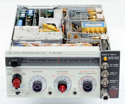 |
The HP 8555A Microwave Spectrum Analyzer Plug-in |
At this point in our microwave division history there was a lot of focus on this family of spectrum analyzers and a high customer demand for them. We had several other analyzers in the planning stages. We were learning customer needs and making instruments that would satisfy their needs. We were doing important stuff. So, hang onto your hat. . . you haven't heard the last of my spectrum analyzer story. It was good these 8552 and 8553 design changes were pretty well completed by May of '69. Because there was a serious need in Rit Keiter's section for a product designer. I was assigned to Rit to help do the product design of the 8555A, another spectrum analyzer.
Rit had a fairly large group of engineers (about 6 or 7) that had been doing circuit design for the 8555 for over a year. He had one product designer that had been working on the front panel layout and calibrated dial assembly along with Jack Magri, the industrial designer.
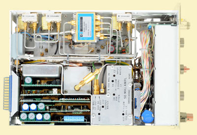 |
Top inside View of the HP 8555A Microwave Spectrum Analyzer Plug-in |
This band switch had about six different positions and a different scale for each position. The 8555A was another spectrum analyzer plug-in that covered beyond 20 GHz (Gigahertz). The front assembly was perfect and well engineered. But Rit was totally frustrated in that the assigned product designer had not done any internal design layout or planning. He had not determined how this instrument was going to go together nor was he able to provide PC board blank sizes so that boards could be laid out allowing circuits to be tested and evaluated. Rit desperately needed product design help. His schedule was starting to slip so I was assigned to help.
It didn't take me long to interview each of the circuit designers and get a feel for their space needs board areas and any special components that take up space. I observed and took dimensions of their special components and studied the block diagram for my layout. I made a full-scale mockup of the plug-in including special housings for oscillators, filters, routing of semi-rigid coax cable and circuit board requirements. I got everyone to agree that the layout would work. Then I created board blank drawings so they could get boards started. I was Rit's hero. He was so happy that things were moving forward on his project. The other product designer was finishing up his panel design and documentation and I just focused on everything but the front assembly. We agreed on where we would interface our designs and our plan and working relationship worked out well.
While waiting for parts from the model shop, Rit asked me to work on a 1.5 GHz notch filter design and a new center post for the second local oscillator cavity in the 8555. This was more of an electrical design but its performance was dependent on physical parameters. It was logical to have a mechanical person contribute to the design. It was fun and interesting. Rit showed me how to calculate the size of the mechanical components to get the desired frequency right on. He showed me how to measure the performance of the filter and oscillator. I really enjoyed working for Rit. I have a lot of respect for him. He is brilliant regarding electronic stuff, he loved flying his airplane, he loved riding his motor cycles. He was a young engineer but more like a fun and smart kid with a good sense of humor.
As you recall, several years ago there was no way that we would be allowed to design an instrument using PC boards. We had so many warranty problems with them that Packard outlawed them until we could make them much more reliable. The PC fabrication technology continued to improve and soon we had two-sided boards with plated-through holes. Then we had four-layer boards with plated through holes. I'm pleased to say the 8555A is the first instrument developed at HP that used a six-layer board with plated through holes. It was a small mother board (about 5X6 inches) designed to accommodate five very dense plug-in boards. It had about 90 connections to the board edges. The 8555A was a very dense packaging challenge. It worked well and was released to production about July '70. Both Rit and our Division Management were happy that it passed all the tests was released to production on schedule.
Back at the lab, John Page took Rod Carlson's place as lab manager when Rod moved up to be Microwave Division manager. John was a splendid, bright, helpful engineer and manager. John gave me my performance evaluation about March 1970. John assigned me to work on a preliminary design of another spectrum analyzer plug-in, 8556A and do some consulting on another product, the 8729A. I can't remember any details about the 8729A and what it was supposed to do.
Thin-film hybrid microcircuits were just becoming popular about 1970, especially in high frequency RF circuits. Our lab came out with a family of Wide Band Amplifiers. This family was the 8447 "A" through "F." They had various gains, bandwidths and connector configurations. These were a fairly simple product design job requiring a small Clement system housing, a power supply, panel, cables and connectors.
About August '70 I got assigned to Tom Grissell's section to help design the 8444A Tracking Generator. This new generator would cover a higher frequency range than the 8443A released earlier. I worked with Tom and his group a couple months on the project and due to medical problems, Tom decided he didn't want to be a project leader and that project was canceled. I was disappointed because I thought the project was going along well and it would be a contribution to our product line. There may have been other extenuating circumstances that I don't know about.
About this same time I was asked to review the cooling of the counter in the 8443A. HP was having field failures due to temperatures climbing too high in the counter section. The design was such that there was no heat-sinking nor convection cooling of temperature sensitive components. My solution was to add a very small Hall-effect DC fan motor just outside the counter box and force air in the box and across the sensitive components. The solution worked well and we had no additional temperature failures that I'm aware of.
About April '69 I got a call from Hank Taylor who worked at HP, about helping out at a nearby company called Finnigan Instruments. The founder of Finnigan Instruments was Dr. T.Z. Chu. They made Mass Spectrometers. That was before HP got into the Mass Spectrometer business. Their lab was located right down Page Mill Road on Hanover. I often passed it on my way home. It was no trouble to stop in at Finnigan after work, meet with their engineers and discuss their project and problems, take the information home, work on solutions and the next day stop by and discuss a workable approach. I consulted with Finnigan for about two years to February '71.
I started with Finnigan at $10.00 per hour. I thought that was pretty good pay since I started with HP at $1.80 per hour. While waiting in the cafeteria lunch line one day with Rit Keiter he asked if I was doing any consulting. He asked what I was being paid which I thought that was a little forward and none of his business (but I'm glad he asked.) He said, "Ten dollars and hour, that's ridiculous, you are worth much more than that!" So when I completed one project at Finnigan and they wanted me start on another, I agreed to help them but the pay had to be increased from $10.00 to $25.00 per hour and it had to be retroactive to three months earlier. They went along with that plan and thanks to Rit, I made more funds than expected. That was one thing I liked about Rit. . . he came right out with it on any subject.
While at Finnigan we accomplished some clever designs mainly on a new controller for their Mass Spectrometer. I learned a lot working with those folks on a part time basis. I was careful not to allow outside consulting interfere with my HP schedules and design activities. In any case, during my free time away from work, I would be spending time building electronic stuff and experimenting in my workshop at home. I thought if I could be paid for this additional electronic fun and work. . . what could be better than that?
We were all outgrowing our bicycles and because someone stole the kid's bicycles from behind our fence and next to the garage, we purchase several new bikes. Each of us went to the bike shop of our choice and picked out the make, model and color that was just right for each of us. Needless to say, I built a lockable bike shed for storage of the four new bikes.
About mid '71 someone parked their new car, a Porsche 914 on the street next to our home. I'll never forget it. . . a bright yellow one and so handsome in design. Its engine was behind the front seat and the solid roof panel could be removed and stored in the rear trunk. It was small and very stylish. I called Donna to come out to see it. We both fell in love with that car. We had to have one. We went to Anderson-Behel Porsch-Audi, talked to the folks there and made the purchase. We got a white one. Right away we put the roof in the trunk space and drove up to Sun Valley Idaho and into southern Washington for a test drive and mini-vacation.
Coincidentally, we entered Sun Valley Idaho at the same time a Porsche Convention was breaking up. We couldn't understand why we were passing so many Porsches on our way to Sun Valley. They'd flash their headlights and wave. We thought they were congratulating us on our new handsome car purchase? We finally figured it all out.
Here is a short story about the Porsche battery problems. Several years later we needed a new battery for the Porsche and it was time for a lube. We took it to a local Porsche service shop in Palo Alto. We arranged for a new battery to be installed and we walked home. I went back to pick up the car a few hours later and the mechanic was embarrassed to show me the car. He lubed the car and replaced the battery but he also dented the front hood and smashed the left yellow directional signal light. It turns out that after replacing the battery he wanted to start the car to ensure that it was installed correctly. He reached through the front window, turned on the key, the car jumped forward (because it was in gear) and it smashed into a VW that was up off the ground resting on supports. It knocked the VW off the supports and we all are lucky no one got killed or injured. Our car got banged up and they later repaired it, but it was difficult to show Donna her damaged car that afternoon.
Things are really getting serious now. John Page assigned me to Ray Shannon's section to assist on the product design of the 8640 Signal Generator. Bill Bull, a mechanical engineer was doing the mechanical design of the Cavity Oscillator and mechanical Tuning Dial for this product. That was a full-time job for Bill. I was assigned to do the remaining product design. Bill and I agreed how and where our designs would meet and that worked well. Bill was a fine engineer and I was sad when he left HP after this project and went to work for Apple Computer.
Ray Shannon was an interesting and very bright project leader. When I started on this project, Ray and I got along very well. There were a lot of strange and wonderful packaging challenges required to accomplish this design. About eight months after working with Ray on April '71, he was to give me my annual performance evaluation. I'll never forget it. Most evaluators have typed, legible and readable copies of the evaluation to discuss during the evaluation process. Ray handed me his evaluation copy and I looked at it but couldn't read it. His writing was small and bunched up and the copy was a very poor Xerox copy.
I was so embarrassed when I handed it back to him and said, "I'm sorry Ray but I just can't read the words." I didn't want to embarrass him nor did I want to get poor marks in cooperation. But I just couldn't make out the words. He obligingly read it to me and we discussed each item as was the tradition. I still have that evaluation in my notebook and still can't read it without the aid of a magnifying glass and steady hand. I was looking at this old review and it says, "Bob is the most competent, creative, productive product designer that has been my pleasure to work with in my twelve years experience and the success of our project will in no small way be a result of his design efforts." I was quite pleased and flattered with those kind words even though I never liked being evaluated nor the evaluation process in general. I could write several pages just about evaluations, the positive benefits and inherent problems.
The 8640 was designed to take replace the HP-608 which HP had been successfully selling for over 20 years. The 608 was a signal generator designed using vacuum tubes. It was large, heavy and expensive but very good at what it did. The 8640 was all solid state and was designed to be smaller and with more features and capability than the 608 but keep the same spectral purity of the output signal as the original 608.
Before I got on the project, Ray Shannon spent some time communicating with Dan Derby, one of the Microwave Industrial Designers. Between them, they came up with a general front panel layout. At first glance it looked good. All the major controls were represented and logically placed. My philosophy as a product designer was to try and work within the aesthetic restraints proposed by the Industrial Designer. If the stuff behind the panel just wouldn't work or fit, then the industrial designer and I would meet and we'd come up with an alternate mutually acceptable panel layout that would accommodate the human factors as well as be practical layout for the required hardware. Working with Dan was always good and his original 8640 panel plan (with minor adjustments) worked fine from a product design standpoint.
The 8640 was packaged in a System 1 (Clement) cabinet that measured approximately 16" wide X 16" deep X 5.25" high. We had several assemblies to fit into that volume. Most of them had to relate to Dan's front panel.
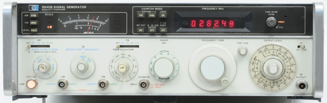 |
The HP 8640B Signal Generator |
The 8640B was the most densely packed instrument because it had a counter assembly with six push-button switches and frequency readout including a time base vernier. There was also a meter assembly with a meter, three annunciators and three switches. Also an output attenuator, coarse and fine tuning assembly, frequency range switch, FM deviation switch, modulation frequency switch, audio output switch and PC slide switches to select AM, FM modulation and RF on/off. There were also front panel connectors AM, FM and Pulse input/output, counter input and RF output. In addition at the rear of the instrument was the modulation amplifier assembly, power supply, and a fan driven by a DC Hall-effect motor. All of these assemblies were designed to be a size and shape that would fit within the box, interface to the front panel and provide enough internal volume to accomplish what is required in each assembly. As I write about it, it doesn't seem possible. But we did it.
This was a big project. There were 13 engineers involved for more than a couple years. That's over 26 man-years to complete this product.
From a mechanical standpoint the 8640A/B was the most fun and challenging project that I worked on at HP. I could spend several pages describing the cams, levers, gears, housings, castings, extrusions, and moldings that we designed and tooled to make this fine signal generator. Since this was a totally new signal generator, designed into a smaller package, it was difficult to borrow parts from existing products. As a result most of the fabricated parts were unique to the 8640A/B. Just for fun, I'll list the quantity of unique and complex parts below:
| 1 | - Custom die castings | 10 |
| 2 | - Plastic molded parts | 12 |
| 3 | - Printed circuit boards | 28 |
| 4 | - Special plastic gears | 18 |
The instrument was split down the horizontal center with a mother board and had smaller boards plug into that from both top and bottom. In order to minimize wiring, many of the interconnections were accomplished by using PC boards. The lower power supply motherboard was connected to the center motherboard with the aid of a riser board. The riser board approach was used in both the counter and divider/filter assembly to interconnect their main boards.
The general circuit approach was to start with a Cavity Tuned Oscillator operating in the 230-550MHz range. Then to get lower frequencies these frequencies were divided down in steps of 2 (divide by 2.) Then the signal was Amplitude Modulated, if required. The divided signal went through several RF Filters to smooth the signal. This divider/filter assembly consisted of one section of dividers and another section of filters. The filters had to be shielded from the dividers and switched in and out depending on the desired frequency coverage determined by the range switch. Well, needless to say, this got very complicated from a packaging standpoint.
We had a Frequency Range switch on the front panel that the operator would rotate to select his desired frequency band. When rotating the switch, several things had to be accomplished. It had to: 1) rotate the mechanical tuning dial in the 8640A to display a different range, 2) select and switch in the desired frequency divider and filter and 3) deselect the unwanted frequency divider and filter. In switching in and out these very high frequencies it was important that they be shielded and physically separated from each other. If not, we would have serious circuit interaction and cross talk.
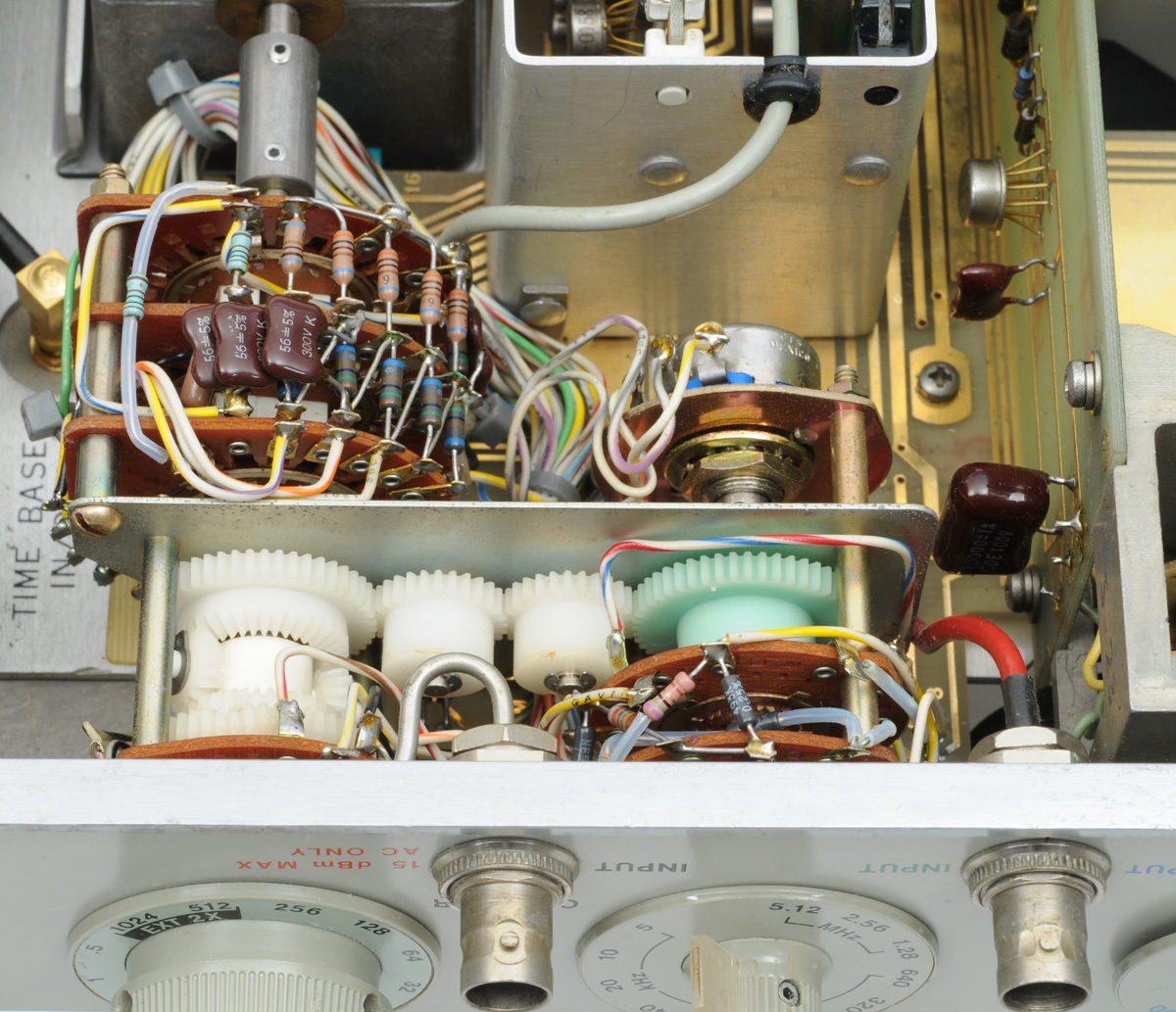
 |
This range switch had multiple complex switching functions |
The solution to the above problem was to design the filter board so that it was mounted on a flat surface, had wide traces where switching would occur and the traces were gold plated. Then we designed a long molded Lexan bar that precisely retained eight gold-plated springy contacts that would touch down on the switching traces when the Lexan bar is set in place. By shifting the position of this bar lengthwise, the proper switching would occur. We had six of these switch-bars in the filter section that had to be positioned precisely each time the band switch was rotated. This switching required that all 48 contacts would dependably make and break at the proper time. That was 48 contacts total and any one, not making contact, would cause signal dropout problems.
In order to control the position of the bars I designed some rocker arms that inserted into a snug fitting recess in the bars. I designed six different cams that controlled the left, center, and right position of the rocker arms as the switch was rotated. Now, when rotating the range switch, the cams were rotated which actuated the rocker arms and that in turn moved the slider bars to the left, center or right and did the appropriate switching depending on the frequency range selected. This design worked surprisingly well and was a fun design experience.
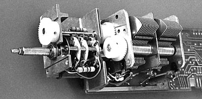
Both the Audio Oscillator and Attenuator design was similar in front panel indication. If one rotated the center shaft of either switch it would cause a recessed dial behind each switch knob to rotate indicating audio frequency or output attenuation. To accomplish this we had a gear attached to the rear end of the center shaft. That gear mated with a gear on an idler shaft, and rotated the idler shaft which then (by a pair of mating gears on the other end of the idler) rotated the appropriate dial. The center shafts also rotated the variable resistors to control audio frequency or output level as desired. The output level was calibrated in volts, millivolts and microvolts. The audio oscillator dial was calibrated from 20 to 200 (with switch positions of X1, X10, X100, X1000 and X3000. That provided an audio oscillator range from 20Hz to 600kHz.
 |
HP 8640 Gear Box Detail |
We wanted the RF range of the 8640A/B output attenuator to cover from +20 to -140 dbm in 10 dB steps. At the time our standard 355B attenuator covered the range of 0 to -120 decibels in 10 dB steps. So it was necessary to add several more switch positions and another attenuation section to the 355B attenuator. The number of positions went from 13 to 15 plus the addition of a vernier potentiometer and switch wafers on the rear of the switch. This modification required that all the cams and detent in the 355B attenuator had to be redesigned. A fairly major modification but it all worked out OK.
One item that was poorly selected was the many required gears to accomplish our needs. Because of their low cost and ready availability we decided to use nylon gears. These gears were just molded nylon. We had our model shop drill and tap the gears for set screws to secure them to switch and idler shafts. The gears worked fine for a while but later, after environmental tests, the nylon dries out and splits at the tapped hole causing it to slip on the shaft. The solution to that problem was to have the gears molded over a brass knurled brass bushing. Then we could drill and tap the gear and bushing and it would hold quite well. The added bushings increased the cost of each gear about five times. Only in our most critical applications we specified the brass bushing.
A very special design was the Delta Frequency and Band switch. I shouldn't even attempt to describe it but will. For electrical reasons two switches were ganged so that rotating either one of them caused additional switching to be accomplished on a third set of switch wafers. This complete assembly consisted of a front panel knob rotating a rotary switch with one wafer of switching and on the end of that shaft we had a coupler to another shaft that rotated the cams which rocked the rockers that positioned the sliders. There was another knob rotating a second rotary switch and two wafers of switching. That switch had an inner shaft that rotated a vernier potentiometer mounted at the rear of this switch. The two switch shafts were coupled together using seven gears. One gear on each switch shaft, two idlers and one planetary gear set of four gears rotating a third shaft of three wafers of switching. I'm sure that description was as clear as mud. This switch was fun to design and worked as intended. When this switch was assembled it was important to align all the switches and cam shaft at position #1 before tightening the gear and coupler set screws.
I loved designing rotary switches. I got lots of experience doing that in the Oscilloscope lab and more experience working in Magnetic Recording lab. Oak, Centralab and Grigsby were the rotary switch supplier of the day. We bought most of our complicated rotary switches from Oak. We even had a prototype switch assembly area in our lab to make weird and wonderful new prototype switches.
It seems that an engineer's best guess doesn't always pan out. It doesn't really matter if the engineer is a lab manager, section manager, project leader, circuit designer, or product designer. No matter how careful and thoughtful ones plans might be, due to unforeseen inputs, reduced requirements or other circumstances the plans change. What am I talking about? In product design, I like to design the product to utilize the internal instrument space uniformly and efficiently.
We did a pretty good job in the 8640A/B except in the modulator assembly. Early on it appeared we required more PC Board space then we eventually used. The modulator housing has space for five boards and we completed design with only two boards in place. Toward the end of this project, I checked with Shannon and Page to see if I could redesign the housing to simplify that part, make it lower cost and made better use of the wasted volume. They both agreed that they didn't want to upset the schedule by doing a small redesign. I tended to agree (mainly because they were my bosses) but I'm sure I could have made the changes without messing up the schedule. Oh well. . . that's the way it goes sometimes.
The counter assembly in the 8640B was a fairly simple product design. Since it had a frequency readout in the front, it had to be positioned toward the front panel right behind the front window. It was designed to fit in a clamshell cast housing. To get power from the motherboard we utilized a rectangular connector with about 24 gold-plated contacts. This connector was sandwiched between two PC boards. When the counter was screwed in place contacts touched down against gold-plated traces on top of the motherboard and against gold-plated traces on the underside of the counter board. Cooling and shielding the counter was an issue. Both ends of the counter were designed to be open but inserted into recesses in the ends was an aluminum honeycomb material that allowed maximum airflow and good shielding from the high frequency signals inside the counter. Heat-sinking the display LEDs was accomplished by designing a cast aluminum heat-sink bar that spanned the width of the window and between the LEDs and their sockets and attached to the counter housing. This provided good heat flow from the display to the housing.
Our industrial designer, Dan Derby, was teaching a couple of classes at Stanford University. After the 8640A/B was designed and in production, In late '77 Dan was discussing the design and manufacture of the 8640 with a couple professors in the mechanical engineering department, Ernie Chilton and Phil Barkan. They decided it would be interesting for the ME-103 class to learn about the design of the 8640. I brought an 8640 over to Stanford and spent an hour telling the class why anyone would want one, what it's for, why we designed it the way we did including many of the mechanical design details of the project.
It was a fun experience for me to lecture at this prestigious university. The presentation was well received by the students. Professor Barkan decided to make a class project of the 8640 if HP would allow it. He asked for samples of some of the more complicated parts and copies of their drawings for study. The class spent several months studying the 8640. The class studied the drawings in detail and later they were taken on a tour of HP casting and plastic molding shops. At the end of the course, each student wrote a report about the tour of our shops and many manufacturing details. One of the students found an error in one of my drawings. I thanked the student and corrected the drawing. Professor Barkan sent me some copies of the student's reports and also wrote a couple thank-you letters to me and Bob Guisto of HP. Bob presented a discussion of the tooling design and build for some of the molds and dies for the 8640.
 |
This switchable power line module with proper line transformer could adapt to 100, 120, 220 and 240VAC |
In parallel with the 8640A/B product design, I was asked to design a 11687A 50 to 75 Ohms Adapter and a 11690 Frequency Doubler to be used with the 8640.
In parallel with the above designs, Jack Magri (our industrial designer) and I put our heads together to come up with a Four-Voltage Power Line Module. This module would be used on most all HP instruments that plug into the wall for power. It was designed to mount on the rear panel of the product. It contained a fuse, fuse mount, fuse extractor, a fuse access door, an interlock to be sure to remove the power cord before accessing the fuse, a four-way switch to select the available line voltage and a connector for the power cord. This module along with an appropriate power transformer would allow the user to operate the instrument at four voltages. They are: 100V, 120V, 220V, and 240V. This was a fun project and took several months to get it all together, tested, evaluated, plastic molds made and released to production. Two Power Line Module designs were needed. One included RF line filter components and the other was a non-filtered version. This module became a corporate wide component to facilitate the same product to be used across the globe. Some countries have 100 Volt AC line and some others have 220 VAC line. It was very popular and was not only used by HP but used by many other electronic manufactures on their products.
After the 8640A/B project was completed and released to production, I was assigned to Doug Rytting's section about February '73 and did some preliminary design on plug-ins for the 8672A Synthesized Signal Generator. I worked on the the 8671A/B control unit and later transferred the project to Santa Rosa about 5/1/73 then I worked on the 86710B RF unit for a few months then transferred that project to Wally Rasmussen's section. In development of new products the model numbers change more often than I'd like so I may have the above model numbers mixed up.
While in Rytting's section I was assigned to Hugo Vifian and his team. Before I knew it, I was asked to help design a new Network Analyzer. Meeting and working with Hugo and his guys and on such an interesting product was the answer to a prayer. This project was the 8505A that was comprised of several assemblies. They were the 85050 Source Receiver (Dan Harkins), 85055 Display Control (Hugo Vifian) and the 85052 Mainframe (can't recall his name?).
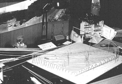 |
Slope profile of our Santa Rosa home building lot |
About this same time that I started working with Hugo, the microwave division split and the move to Santa Rosa was hot and heavy. Many of our Microwave Division engineers were moving to Santa Rosa. It came as quite a surprise to me when I learned that Hugo's project, most of Hugo's team and Hugo were moving to Santa Rosa. I discussed this situation with Donna and we decided to spend a week up in Santa Rosa to see if we wanted to make it our home. We packed our two kiddies in the car along with our four bicycles and headed to our motel in Santa Rosa. We biked and drove all over the place. We looked at homes and lots. We talked with realtors and builders. The kids were not enthused about the move. It meant a change in schools and making new friends. Donna was just slightly enthused especially when we were looking at lots and discussing plans to build a dream home on a Santa Rosa hilltop.
After serious discussion we decided we liked it enough to move there so we found and purchased a half-acre lot on the corner of Alta Vista and Happy Valley roads. We had quite a view toward the west from this lot. We had the lot surveyed and talked to a couple builders. I was enthused about our new lot. I went to the Geological Survey in Menlo Park and purchased an aerial view of that area of Santa Rosa including the lot. Using the surveyor's drawings I built a model of the lot using balsa wood. The model was intended to show a scaled down size, shape and slope so we could consider how our new home was to be designed and built. I was more and more enthused about moving so I could continue working with Hugo and his project.
A few days later our property tax bills came for both the Palo Alto and Santa Rosa property. It was clear to me that the property taxes were much higher in Santa Rosa. We surmised that was because Santa Rosa was still a growing community and schools were being built, roads were being put in and various utilities needed to be added.
Several thoughts caused us to reconsider this move:
It didn't take us long to decide that we were better off to stay where we are, so we put our Santa Rosa lot up for sale with the same realtor that sold it to us initially. Within a few days he found a buyer and we made a couple thousand dollars on the completed transactions. With those funds from the lot sale, I paid off our remaining home loan for 1300 Cowper St.
I've often wondered how our lives would have changed if we made the Santa Rosa move. Many things we accomplished and folks we met were a result of staying here in Palo Alto. I'm sure we would have made other new friends and have different experiences if we moved. That Santa Rosa decision was another "Y" in life's road. We'll never know what might have been. Our (actually, my) greatest incentive to move was to be a part of the group that were developing this new Network Analyzer and be able to work with and for this good guy, "Hugo Vifian." Actually, I was on his project only a few months but we've been friends and have kept in touch these many years. Forty years later after we both retired from HP, we actually worked together again. The company? Anritsu of Morgan Hill and the products we worked on were network and spectrum analyzers. That's a story for another day though.
About 5/8/73 I was assigned to work with Rolly Hassun on the 8661A and later renamed to the 8662A. This was a pretty sophisticated Frequency Synthesizer. I'll describe it and other activities, in some detail, in the next section.