

| Click-in for High-Resolution Display = 1024 x 1200 pix @ 150 ppi |
 |
The HP300A Harmonic Wave Analyzer |
(From the Original INSTRUCTION & OPERATING MANUAL)
The Model 300A Harmonic Wave Analyzer is a selective voltmeter designed to measure the individual components of complex waves. The selectivity can be varied by means of selective amplifiers to measure either closely or widely spaced harmonics. The instrument covers the audio spectrum from 30 to 16,000 Hz. It has a wide voltage range so that full scale readings may be obtained from 1 millivolt to 500 volts.
The Model 300A is well adapted to the measurement of the harmonic distortion in audio frequency equipment of all kinds, broadcast receivers, transmitters; to determine the harmonic components in ac machinery and power systems; to the study of induced voltages on telephone lines; and to measurement of hum components in rectifier circuits.
Other uses include the study of noise by integrating portions of the spectrum with the selectivity control adjusted for a wide pass band and the checking of wave filter characteristics with maximum selectivity.
The Model 300A is also useful as a device to measure the amount of cross or intermodulation products generated by the simultaneous transmission of two frequencies by an audio system or to measure demodulation of a modulated wave applied through an audio system.
According to John Minck HP Narrative, the HP 300A Wave Analyzer was probably the second instrument designed by Bill Hewlett, in 1941. Chuck House, in "The HP Phenomenon," considers that is was Hewlett's next major product contribution, aside from variations of the original Audio Oscillator. Michael S. Malone in "Bill & Dave" ranks the model 320 distortion analyzer as the second Hewlett Packard product, after the audio oscillators, and before the 300A. Today, Minck agrees with Malone that the HP 320 came first. That makes sense because it is a simpler instrument, in that it measures TOTAL distortion, and does not have to perform the difficult job of separating out the harmonics. The 320 was intended for distortion measurements at 2 or 6 specific frequencies, instead of being tunable. After setting a reference level, it cleverly notched out the fundamental frequency with a filter and simply measured the remaining signal distortion products.
Today it is difficult to get an absolute certainty, but more importantly, in our opinion, the 300A could have been probably the very first occurance of what will become later a very common and frequent practice at HP: When you need better measurement, and you can't find the right tool to do the right job... Just built it ! . . .
 |
The HP 300A in the 1943 Catalog |
. . . And there is a great chance that the 300A, before being a "catalog product," was firstly an internal R&D, and production tool designed to satisfy the own need of HP's production of the time.
Considering that the early production at HP was mainly layering onto Bill Hewlett's original audio oscillator variations, enlarging the product line by growing again the limit of the original circuitry would need better and better performance of the equipment required for designing and testing the next product. Audio distortion measurements were also needed on components such as transformers and amplifiers.
One of the most important specified characteristic, defining the quality of an audio oscillator, is its harmonic distortion. Harmonic distortion may be expressed in terms of the relative strength of individual components, in decibels, or the Root Mean Square of all harmonic components: Total Harmonic Distortion (THD), as a percentage in this case. There are two ways to achieve these two kinds of measurements. In the first method, the amplitude of each frequency component appearing in the output of a device under test is measured with a frequency selective voltmeter. In the second method (THD,) the amplitude of a voltage containing harmonics is first measured; then the fundamental is filtered out and the rms value of the combined harmonics is measured. The ratio of the two values, expressed in per cent, is the distortion.
There is a safe bet that during the early 1940s, distortion measuring instrument, of one type or the other, weren't readily available on the electronic market, and even if some existed, they probably didn't have the measurement accuracy targeted by HP.
 |
Using the HP 300A in the 1943 Catalog |
It seems likely that the different techniques were deeply explored by Bill, Dave, and the other early HP engineers, and that consequently a lot of prototype testing devices found more or less thorough development to reach their planed results. Among them, at least two distortion instruments were performing well as soon as 1943, and became salable products included in the first HP catalog. There was one for each of the two method of measurements, the 320A for Total Harmonic Distortion, and the 300A for Selective Level Measurement.
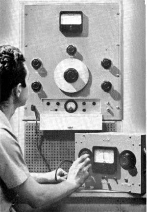
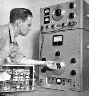
Three photographs, (on the right, top, and bottom of this paragraph,) come from the 1943 catalog.They clearly illustrate the intensive use of the HP 300A for various typical lab activities of adjustment and tuning procedures of different instruments inside HP.
In each of these three pictures the 300A in use has no HP Logo, nor any name plate which were always present on every HP equipment for sale. Another proof of the intensive use of the HP 300A as an internal research tool, long before its marketing rollout.
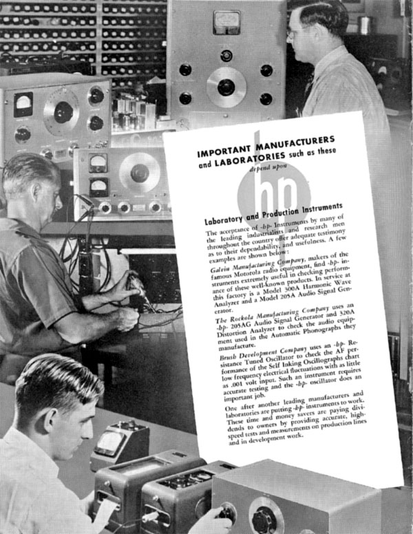 |
Page 2 of the 1943, First HP Catalog |
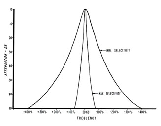 |
Selectivity Characteristics of Model 300a Amplifier |
(From the 1945 catalog)
The circuit of the Model 300A consists of a variable local oscillator, a balanced modulator, a selective amplifier, and an indicating meter. The variable local oscillator modulates the unknown frequency to produce a constant difference frequency. This difference frequency is applied to the selective amplifier, the output of which is then proportional to the magnitude of the unknown voltage. A meter in the output of the selective amplifier indicates the magnitude of the voltage.
The local oscillator is of the resistance-tuned type, providing a very stable, accurate voltage. A balanced modulator is used to eliminate the local oscillator frequency and to keep cross-modulation products very low. The selective amplifier consists of four tuned circuits in which the effective Q is controlled by positive feedback. Negative feedback is also used to stabilize the amplifier. This amplifier has the unique characteristic that its selectivity may be varied over a wide range without appreciably affecting the gain of the amplifier.
| Block Diagram of the HP 300A |
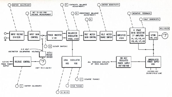 |
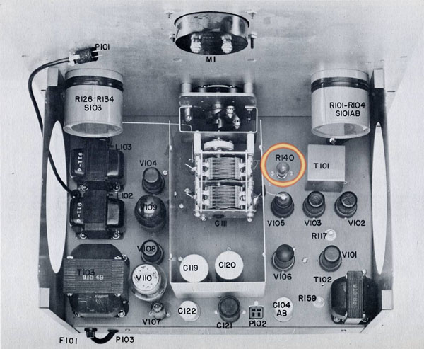
As designed into the Model 200 Audio Oscillator, the local oscillator of the HP 300A uses a 6J7, (V105) followed by a 6F6 amplifier (V106). And like on original Bill Hewlett's patent, the circuit output level is stabilized by a 3 Watts incandescent lamp (R140) in the oscillator-amplifier feedback loop.
| Top Inside View of the HP 300A Bottom Deck |
 |