 |
350A Attenuator
|
Attenuators, Voltage Dividers
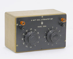
The 350 attenuator was listed for the first time in the 1945 catalog page 28. It consists of two bridged-T circuits. One is a 100 dB attenuator, calibrated in 10 dB steps and the other is a 10 dB attenuator, calibrated in 1 dB steps. The design, made of individually adjusted resistors to ± 0.5 %, results in less than 2 dB accumulative error at full 110 dB attenuation, and a usable frequency range of 100 kc.
Two models were available. The 350A matches a 500 Ω impedance and the 350B matches a 600 Ω impedance. It is interesting to note that at this time the 600 Ω impedance was not yet the standard for audio measurement. It was probably the telephone industry which settled on 600 Ω some years later.
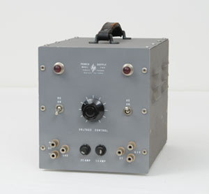 |
The HP 710A Power Supply
|
Power Supply
The very first power supply manufactured by HP was introduced in the 1945 catalog. It was a general purpose source of power for laboratory and production department use. It delivered a continuously variable high voltage output of 180 to 360 volts to the connected equipment, at a maximum load current of 100 milliamperes. A center-tapped, 6.3 volt AC source for supplying a maximum of 5 amps to the test circuit vacuum tube filaments has been included in addition.
The evolution of the power supply product line was slow during the 1950s and 1960s. Among the 260 instruments listed in the 1961 general catalog, only 8 were power supplies. But things would change dramatically by the beginning of the 1960s. After buying the Harrison Laboratory Company in 1962, the evolution of the power supply production was such that it prompted the creation of the Hewlett Packard - Harrison Division. It was later renamed the "HP New Jersey Division."
The quantity of different models of power supplies produced by the HP - Harrison Labs Division in 1966 was such that it generated the edition of a special catalog fully dedicated to power supplies. It was a 80-page catalog, listing more than a hundred different models, and including many tables of specifications, and dedicated application notes, to help the engineer choosing the power supply which will best fit his need.
Harrison power supplies were known for their high performance and sophisticated circuit designs. Founder William Harrison was known for his complex feedback loop circuits which provided exceptionally low ripple and noise, as well as superior output stability. With the rapid transition to semiconductor technology across the globe, new power supplies which treated the special requirements of power transistor circuits were in great demand.
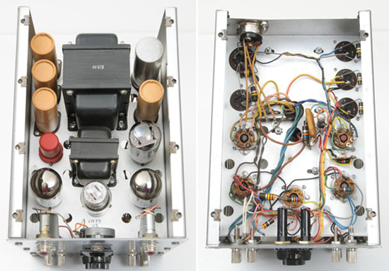
| Top and Bottom Inside Views of the HP 710A Power Supply |
 |
The HP 300A Harmonic Wave Analyzer
The HP 300A Wave Analyzer was probably the second instrument designed by Bill Hewlett, in 1941. Considering that the early production at HP was mainly layering onto Bill Hewlett's original audio oscillator variations, enlarging the product line by growing again the limit of the original circuitry would need better and better performance of the equipment required for designing and testing the next product. Audio distortion measurements were also needed on components such as transformers and amplifiers.
One of the most important specified characteristic, defining the quality of an audio oscillator, is its harmonic distortion. Harmonic distortion may be expressed in terms of the relative strength of individual components, in decibels, or the Root Mean Square of all harmonic components: Total Harmonic Distortion (THD), as a percentage in this case. There are two ways to achieve these two kinds of measurements. In the first method, the amplitude of each frequency component appearing in the output of a device under test is measured with a frequency selective voltmeter. In the second method (THD,) the amplitude of a voltage containing harmonics is first measured; then the fundamental is filtered out and the rms value of the combined harmonics is measured. The ratio of the two values, expressed in per cent, is the distortion.
There is a safe bet that during the early 1940s, distortion measuring instrument, of one type or the other, weren't readily available on the electronic market, and even if some existed, they probably didn't have the measurement accuracy targeted by HP. It seems likely that the different techniques were deeply explored by Bill, Dave, and the other early HP engineers, and that consequently a lot of prototype testing devices found more or less thorough development to reach their planed results. Among them, at least two distortion instruments were performing well as soon as 1943, and became salable products included in the first HP catalog. There was one for each of the two method of measurements, the 320A for Total Harmonic Distortion, and the 300A for Selective Level Measurement.
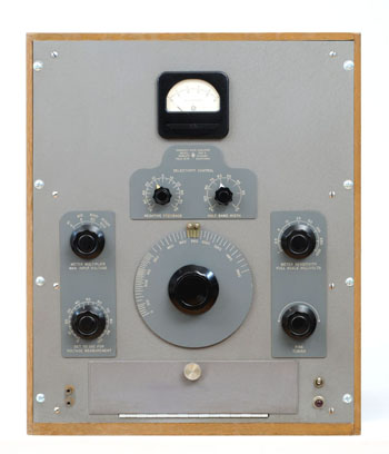 |
The HP 300A
|
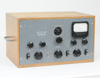
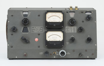
The HP 300A
The Model 300A Harmonic Wave Analyzer is a selective voltmeter designed to measure the individual components of complex waves. The selectivity can be varied by means of selective amplifiers to measure either closely or widely spaced harmonics. The instrument covers the audio spectrum from 30 to 16,000 Hz. It has a wide voltage range so that full scale readings may be obtained from 1 millivolt to 500 volts.
The Model 300A is well adapted to the measurement of the harmonic distortion in audio frequency equipment of all kinds, broadcast receivers, transmitters; to determine the harmonic components in ac machinery and power systems; to the study of induced voltages on telephone lines; and to measurement of hum components in rectifier circuits.
Other uses include the study of noise by integrating portions of the spectrum with the selectivity control adjusted for a wide pass band and the checking of wave filter characteristics with maximum selectivity.
The Model 300A is also useful as a device to measure the amount of cross or intermodulation products generated by the simultaneous transmission of two frequencies by an audio system or to measure demodulation of a modulated wave applied through an audio system.
 |
The HP 320A Distortion Analyzer
|
Distortion Measurement
Also introduced in the early 1940s, the Model 320 just added a T-notch rejection filter to the attenuator described above to make, (as stated in the 1945 catalog description) a simple and convenient device for studying and measuring the harmonic distortion in audio frequency apparatus.
We take the liberty to classify this device as a measurement accessory because at this level it is only a passive device. But the 330B and 325B distortion analyzers and the 300A harmonic wave analyzer, all listed in the same 1945 catalog are a clear testament to the early concern of HP to produce high performance signal analysis instrumentation. Four different instruments dedicated to signal analysis in 1945 are certainly a good explanation to the overwhelming leadership of HP in spectrum analysis which would soon begin in 1963.
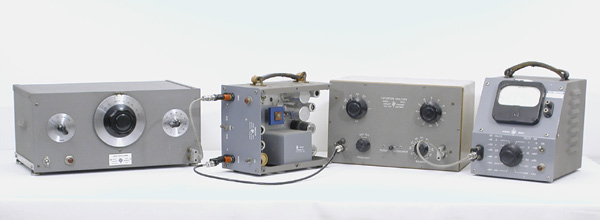
The picture below recreates the amplifier distortion test set suggested in the 1945 catalog page 19. From left to right, a 200C oscillator is the signal source which feeds trough a 450A amplifier under test. At its output the carrier frequency is rejected by the 320 T-notch filter and the remaining harmonic spectrum RMS value is measured in the 2 Mc bandwith of a 400C electronic voltmeter.
| Typical amplifier characteristics test bench of the 50s - Historical reconstruction made with pieces from the collection |
 |
 |
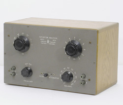
330B Distortion Analyzer
|
Distortion Analyzer
Combining all the instruments shown in the above picture in a single box would result in the 330B distortion analyzer which is presented in the 1948 catalog as follows:
The -hp- Model 330B Distortion Analyzer is capable of measuring distortion at any frequency between 20 cps and 20,000 cps. It will make noise measurements of voltages as small as 100 microvolts. A linear r-f detector makes possible measurements of these characteristics direct from a modulated r-f carrier. The convenience of operation, high sensitivity, accuracy, stability and light weight of the -hp- 330B make it an uniquely valuable instrument for broadcast, laboratory and production measurements. The circuit of the Model 330B consists of a linear r-f detector, a frequency-selective amplifier, a vacuum tube voltmeter, and a regulated power supply. The r-f detector includes a diode rectifier operating in conjunction with a resonant circuit which is tuned to the carrier frequency under measurement. The detector covers a range of 500 kc to 60 mc, and is varied by means of a tuning condenser and range switch which selects one of six bands. The detector may be switched out of the circuit when audio frequencies are used.
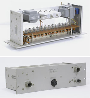 |
460BR Distributed Amplifier
|
Amplifier
Another birth in the measurement accessories category, the 460A wide band amplifier was the first of another long life product line. It was introduced in the 1950 catalog, page 62, but more importantly,
it is the product described in the first Hewlett-Packard Journal,
Volume 1, Number 1, published in September, 1949. The 460A is described as follows on the front page of this first HP Journal issue:
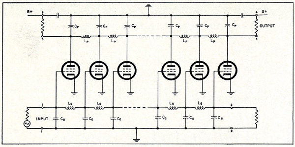
"Recent developments in nuclear radiation measurements have created a need for amplifiers having extremely wide bandwidth or speed compared to conventional video amplifiers. For example, certain photo-multiplier type radiation detectors have output pulses as short as 0.01 microsecond. The new Model 460A amplifier will amplify such pulses with very little distortion and provide suitable output for operating scalers, coincidence devices, or for direct viewing on a cathode ray tube. Although this amplifier was developed primarily to meet these requirements, other more general applications suggest themselves for amplifying signals anywhere in the range from audio frequencies to 200 megacycles. The amplifier can readily be used for extending by tenfold the sensitivity of a peak-reading diode voltmeter or for amplifying the output of a low-level signal generator. The distributed amplifier circuit provides a means for connecting conventional amplifier tubes in parallel so that their plate currents add but their capacities do not. Thus, the bandwidth can be increased beyond the point where the individual tubes have a gain of one, which is the limiting point in conventional cascaded stages."
The amplifier uses 13 x 6AK5 Vacuum tubes in a cascaded distributed arrangement whose simplified schematic is shown below. The specified gain is 20 dB with 200 Ω input / output resistive load with a .0026 µs rise time.
| Basic Circuit of Cascaded Distributed Amplifier - Figure 2, page 2 of Hewlett Packard Journal Vol 1, Nbr 1, September 1949 |
 |
 |
The Boonton Radio 260A "Q" Meter
|
Measurement of Coil "Q"
Another interesting instrument in the chapter of early measurement accessories is the 260A "Q" Meter.
The 260A "Q" Meter is not an original HP design. It is one of the first examples of HP's growth strategy to buy other companies, starting at the end of the 1950s. Hewlett Packard bought the Boonton Radio Corporation (BRC) in 1959. BRC was a well respected RF instrumentation company and had lots of well designed RF instruments in its catalog.
From a technical point of view, the accurate measurement of a coil's "figure of merit," ("Q"), was a major concern in this period of fast growth for the radio and TV broadcasting industry. The demand for RF measurement tools in this period was such that Booton Radio Corporation celebrated the shipment of its 10,000th "Q" Meter in May 1957. (The BRC Notebook Nbr 14, page 7. From hparchive web site)
The main specifications of the Boonton 260A are: frequency range of 50 kHz to 50 MHz; continiously variable in 8 overlapping bands; and a range of "Q" measurement from 10 to 625.
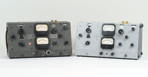
In 1969, the original Boonton Radio 260A "Q" Meter was re-styled to look and feel like current HP instruments, especially in the case color of the time. Because it did not included any technical updates to the original Boonton 260A circuitry, it kept the same Model number, and was simply renamed HP 260A. (the right one on picture below)
The Boonton Radio 260A "Q" Meter on the left.
On the right, the 260A HP restyled in 1969 |
 |
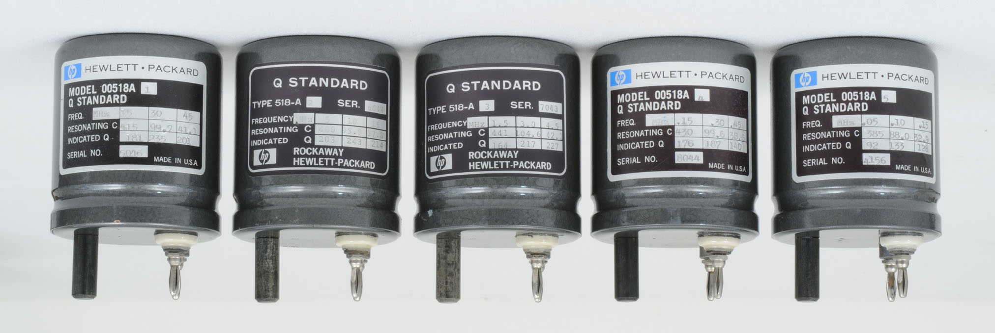
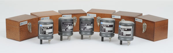
The "Q" Standard Coils Set, with their Original Wood Box
Click-in to Read the Coil Value - High Resolution Picture 2024 x 680 pixels @ 300ppi |
 |
 |
The HP 342A Noise Figure Meter and HP 343A VHF Noise Source
|
Measurement of Noise Figure
Hewlett-Packard's first microwave noise figure meter was the Model 340A, introduced in January, 1958. It featured 2 hard-wired IF frequency selections, 30 and 60 MHz. Fairly quickly, HP got customer feedback asking for other frequencies, because microwave systems were being designed for various reasons, with other higher IF circuitry.
Thus the HP 342A Noise Figure Meter was introduced a year later in the 1959 catalog, and described in the 1959 February-March issue of the Hewlett Packard Journal.
In radio communications, or radar surveillance, the weakest signal that can be used is usually determined by the amount of noise added by the receiving system. This inherent noise of any receiving system is always resident at the very first stage, an rf preamplifier or in the superheterodyne down-conversion stage at the front end. Once passed through that first stage, it doesn't do any good to add amplification, because BOTH the desired signal and the receiver's added noise get amplified together, meaning the signal to noise ratio stays virtually the same.
Thus, any decrease in the amount of noise generated at the first stage in the receiving system will produce an increase in the output signal- to-noise ratio equivalent to a corresponding increase in received signal. From a performance standpoint, an increase in the signal-to-noise ratio by reducing the amount of noise in the receiver is more economical than increasing the received signal level by raising the power of the transmitter. For example, a 5 db improvement in receiver noise figure is equivalent to increasing the transmitter power by 3:l. It is clearly more economical to work on noise figure.
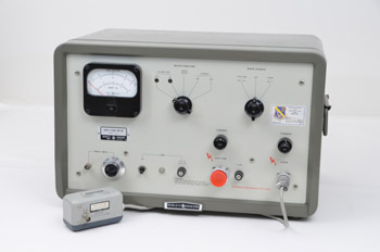
Hewlett-Packard Model 342A Noise Figure Meter measures noise figure as a function of the ratio between the noise output of the receiver under test, compared to a known amount of noise introduced at the input, and to the noise output when the device is terminated in its normal load. The noise input is supplied by a family of calibrated microwave noise sources, either argon or neon gas discharge tubes, or in the case of rf bands, a thermally-limited diode source.
Depending on the Noise Source connected to the HP 342A, the Noise Figure Measurement can be done from 10 MHz to 600 MHz in coaxial systems, and from 2.6 to 18 GHz in waveguide systems.
The HP 342A, at its introduction, was advertised as "A New Instrument Which Speeds Noise Figure Measurements,"
"Receiver and component alignment jobs that once took skilled engineers a full hour are now done in 5 minutes by a semi-skilled worker. Receiver noise figure can often be improved over the best adjustment previously possible. For instance, a 3 dB improvement in receiver noise figure equals doubling transmitter output. Since accurate alignment is easy, equipment is better maintained and peak performance enjoyed regularly."
A good proof of its performance and efficiency
was its 22-year lifetime in the HP general catalog. The Model 342A was still listed in the 1981 catalog.
The HP 342A was finally obsoleted by a brand new microprocessor-based instrument, the HP 8970A, in 1983, which featured measurements of both amplification and noise figure. This was a handy combination, because often in the design of the first stage of a microwave receiver, you are willing to trade off a loss of gain to achieve a lower noise figure.
 |
HP 428B Clip-on DC Milliammeter
|
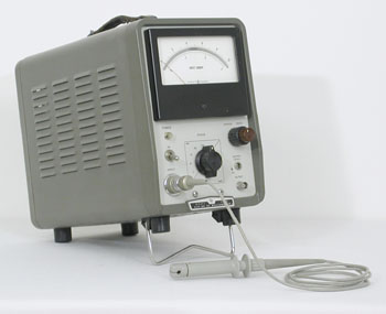
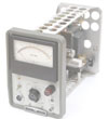
The Clip-on DC Milliammeter
An instrument which could be also listed in the voltmeter chapter, the 428A Clip-on DC Milliammeter was introduced in the June-July, 1958 issue of the Hewlett Packard Journal.
The 428B measurement range goes from 1 milliampere to 10 amperes full scale in a 1, 3, 10 sequence.
The 428B Clip-on DC Milliammeter remained in the HP General catalog up to 1986 and it is still today a very useful instrument in the electronic workshop.
The HP 428 was such a successful product that it was chosen by Bill Hewlett for a special appreciation in the introduction of his book: "Inventions of Opportunity" edited in 1983:
"The instrument described in this article is an example of an old technique used for modern purposes. The principle is essentially similar to that used in a conventional flux-gate compass, i.e., a magnetic amplifier that produces a second harmonic component of the existing ac current. This second harmonic is proportional to the dc flux surrounding the conductor being measured. The use of negative feedback increases the accuracy and stability of the measurement. To illustrate some of the practical problems relating to the design of this instrument, the earth's magnetic field is about three hundred times stronger than the field measured by the instrument on its most sensitive range. The applications for this instrument had obvious advantages, for it could measure direct currents without the insertion of an external instrument or without the load on a circuit of a resistor across which a voltage could be measured.
Like many of our other products, the suggestion came from the outside. One of our senior sales engineers with aviation instrumentation experience had made the comment, "Have you ever thought of using the flux-gate compass principle to create a clip-on milliameter?" That was all that was necessary."
Animation Display: Interior Panoramic View of the HP 428B
Animation |
 |
|
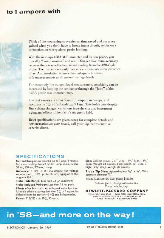
| Dual Page Publicity of the HP 428A in ELECTRONICS Magazine, January 30, 1959 |
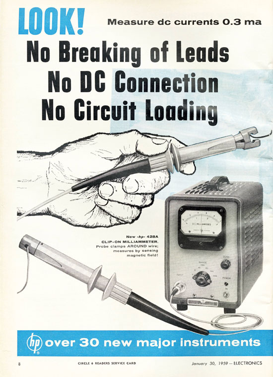 |
| Dual Page Publicity of the HP 428A in ELECTRONICS Magazine, January 30, 1959 |
 |