Evolution of Signal Generator during the 1960 to 1980 Period
The evolution of the signal generator during the sixties was relatively slow. A number of reasons can be listed to explain that. First of all, a lot of signal generators, perfectly matching the market needs, were already in the Hewlett Packard catalog by the end of the fiveties. The 606, 608 and 612 were state of the art signal sources for the measurement of RF, VHF, and UHF receiver performance of the time. The 610 and 620 series covered this same requirement for the lower to higher frequencies of the microwave spectra. All these generators were using vacuum tube or Klystron master oscillator, with High Q or cavity tuning circuits, whose fundamental design gave a guarantee of low noise and high spectral purity signal output.
A real leap forward would need to preserve at least these qualities, and if possible to improve some weakness in the vacuum tube, like for example, the poor stability due to heat dissipation. The obvious solution was the transistor, but the transistor was newlyborn in 1960. The first available commercial production of transistors had very poor high-frequency performance and was very far from satisfying the requirement of the HP Signal Sources product line. So to compensate for this weakness, the HPA Division of Hewlett Packard would make considerable R&D investments to produce RF microwave transistors with the highest performance on the market during the sixties. Research and development of the HPA Division was not limited to transistor so fairly quickly a complete product line of state-of-the-art microwave components would be produced by the HPA division. Schottky barrier, PIN, Step Recovery and IMPATT diodes for use, not only in HP instruments, but also in consumer, industrial and high-reliability applications.
This in-house technology mastery would be a great help during the 70s for HP to preserve their leadership despite growing competition. The HP's know-how in discrete components would evoluate naturally to the Integrated-circuits industry and would have a considerable inpact on the Signal Sources product line and on the new-coming HP computer production up to the end of the century.
1962, Last Evolution of the Klystron Oscillator
 |
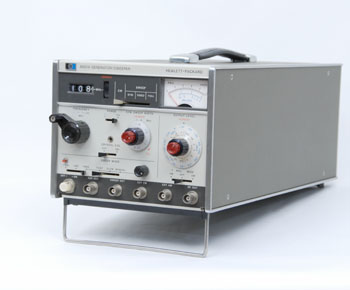
HP 8614A Signal Generator
|
The HP 8614A, and HP 8616A
Signal Generators
The Mechanical Complexity of Klystron Oscillator found its last achievement with the 8614A and 8616A Signal Generators introduced in 1962, and 1963 respectively.
The 8614A was described in the July 1963 edition of the Hewlett Packard Journal. It operates over the band from 800 to 2400 megacycles, and the 8616A, introduced in the 1963 catalog covers from 1800 to 4500 megacycles. Both generators provide an RF power output that is virtually flat (within ± 0.5 db) over their entire range, and both frequency and attenuation are set on direct-reading digital dials. The flat output is obtained by an automatic internal leveling system and eliminates the need for readjusting the output power at each change of frequency, thus facilitating many measurements.
The accuracy, stability, and repeatability of the cavity-tuned klystron oscillator, all depended crucially on the quality of their mechanical design and construction. Mechanical connections to the front panel controls first involved tuning the cavity plunger, and usually required a non-linear mechanism. The 8614A cavity shown below used a cam drive to match the Klystron tuning curve.
 |
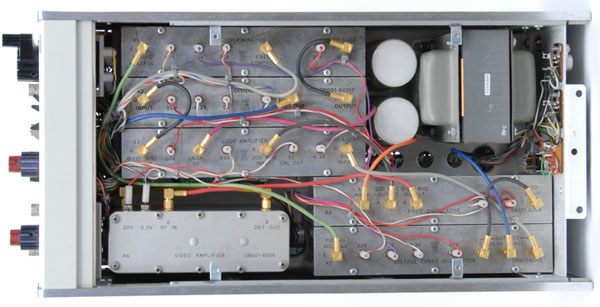
| Inside View of the HP 8614A |
Not Stable Enough ? ... Lock It !
Back to the sixties, and waiting for the transistor to improve its high frequency performance, a lot of engineering was spent in the development of circuitry to offset the vacuum tube weakness.
The first step was to find some way to raize the stability and accuracy of the existing signal generators, and this would be the purpose of the 8708A Synchronizer announced in 1966.
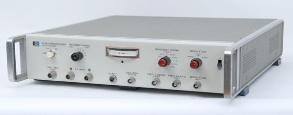 |
| The HP 8708A Synchronizer |
The HP 8708A Synchronizer is a phase-lock frequency stabilizer that allows to obtain crystal-oscillator stability in the 606B or 608F Signal Generator. Phase-locking eliminates microphonics and drift, resulting in a frequency stability of 2 x 10E-7 per 10 minutes, an increase by a factor of 250 of the HP 608 free-runing oscillator. The 8708A includes an ultrafine frequency vernier which can tune the reference oscillator over a range of +/- 0.25% permitting frequency settability to 2 parts in 10E7. This provides a very stable, yet tunable signal generator to satisfy the critical performance required by SSB and narrow band receiver. The considerable advantages of Single-Sideband transmission was taking over the classic AM by the end of the sixties.
 |
The HP 3200B VHF Oscillator
|
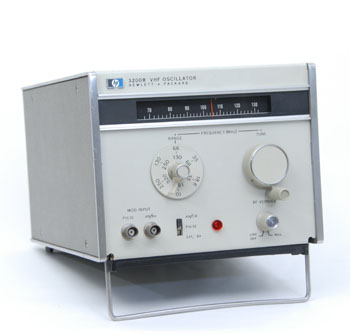
The HP 3200B VHF Oscillator
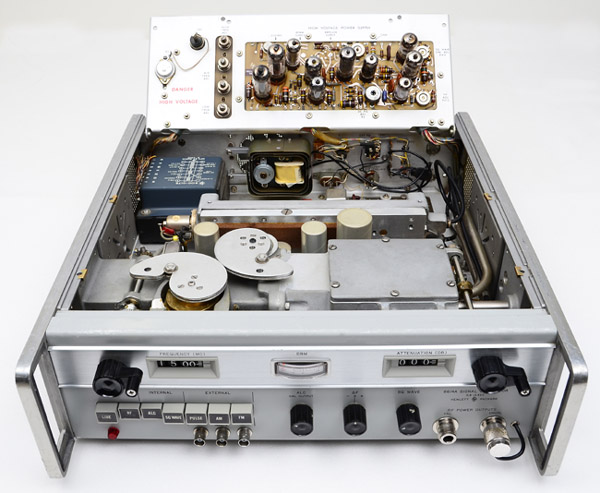
One of the last VHF Oscillators, using only vacuum tubes, was the 3200B produced by HP in 1966 . The HP 3200B was a low cost very simplified version of the 608 generator for testing receivers and amplifiers, and driving bridges, slotted lines, antennas, and filter networks.
The 3200B could also serve as a local oscillator for heterodyne detector systems and as a marker source for swept systems. The 3200B covered the frequency range of 10 to 500 MHz in six bands. The maximum power output was 25 milliwatts up to 500 MHz, and a 120 dB attenuation range was achieved by a Waveguide-Beyond-Cutoff attenuator. An optional accessory frequency doubler probe, HP 13515A, provided additional frequency coverage from 500 to 1000 MHz.
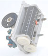
Animation Display: Panoramic View of the HP 3200B Master Oscillator
Animation |
 |
|
 |
HP 8601A Generator - Sweeper
|
The HP 8601A Generator-Sweeper
The HP 8601A is first of all a sweep generator, but the advancing transistor technology of 1969 gave it some signal generator characteristics which began to compete with previous vacuum tube signal sources.
The 1969 catalog introduces the HP 8601A as a "Two Instruments in One" ultra-versatile broadband source. Covering 100 kHz to 110 MHz, the 8601A Generator / Sweeper combines the high linearity and flatness of a precision sweeper with a signal generator's frequency accuracy and wide range of calibrated power levels.
As a signal generator, the 8601A offers excellent CW characteristics with +/- 1% of frequency dial accuracy and a wide range of continuously adjustable output power levels accurate to +/- 1 dB from +13 to -110 dBm. A power output meter is calibrated in both dBm and rms volts into 50 ohms.
As a sweeper, the HP 8601A will be described in more details in chapter 4 of this Signal Source & Generator "Quick Tour."
As shown in the picture below, the 8601A is one of the first HP instruments to take advantage of a perfect modular construction. The reduced size of components and development of the first generation of thin-film hybrid-microcircuit on sapphire substrate, had made it possible to package the RF sections of the instrument in individual modules. Two major benefits ensued. First, RFI leakage could be kept extremely low by running shielded transmission lines between modules. The generator/ sweeper's RFI leakage was so low that it could provide input levels as low as one microvolt in receiver sensitivity measurements without RFI degradation. Second, modular packaging simplifies troubleshooting and servicing; malfunctioning modules could be identified and replaced rapidly.
 |
| Inside View of the HP 8601A Generator / Sweeper |
 |
The HP 8654A Signal Generator and Companion
Synchronizer / Counter HP 8655A
|
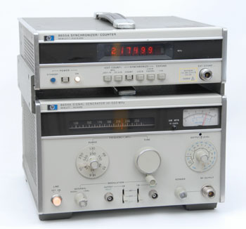
The HP 8654A Signal Generator
and HP 8655A Synchronizer
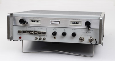
Model 8654A is a compact, low-cost, solid-state signal generator that provides automatically leveled power from +10 to -130 dBm over a frequency range of 10 to 520 MHz.
The 8654A was introduced in the 1972 catalog. The 8655A Synchronizer was introduced four years later in 1976. The combination of the two instruments was a low-cost solution, approching the performance of the HP 8640, itself introduced in 1973.
The HP 8654A was the first, full transistor, real substitute to the HP 608 Signal generator. It can be considered as the next step in the transition from vacuum tube to transistor in signal sources design. An in-depth analysis of the step by step evolution of the various circuitry used in a signal generator was made in the 1974 "Signal Generator Seminar." A PDF copy of the book is downloadable from the link below.
1974 Signal Generator Seminar
A very complete analysis of the advancements in signal generators design from the 608 to the 8640, and in synthesizers design from the 5100 to the 8660, was made in the 1974 Signal Generator Seminar. The document lists the advantages and drawbacks of the various RF signal generation technologies available in 1974. From the master oscillator to the output connector, the different approaches are discussed and their impact on the final performance analysed.
PDF File of the 1974 Signal Generator Seminar (90 pages 12.6 Mo)
1973: The HP 8640... Another Step Forward
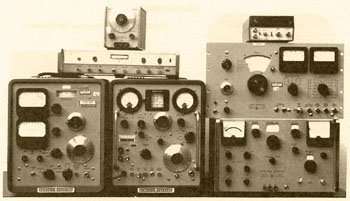 |
Photo from the 1974 HP Signal Generator Seminar
Courtesy of Hewlett-Packard Company
|
This picture comes from the 1974 " Signal Generator Seminar" downloadable from the link above. It was commented with the following text:
"To dramatically illustrate how far signal generator design has come in the last decade, here is the equipment replaced or partially replaced by the new HP 8640B high performance signal generator plus a frequency doubler. (Left to right, top to bottom: 204 function generator, 5300 counter, 8708A synchronizer, 606 signal generator, 612 and 608 AM signal generators, and 202 FM signal generator.)"
1973: The HP 8640, A Solid State VHF Signal Generator
for the 1970s' Exacting Requirements
In 1973, for about 20 years the familiar HP 608 vacuum-tube signal generator had been the first choice instrument for critical RF testing. From the start, the 8640 program aimed to produce a solid-state generator which, at the minimum, would match the CW performance of the old vacuum-tube generators. The spectral purity of a vacuum-tube oscillator and the freedom from aging effects characteristic of solid-state oscillators were combined in the new 450 kHz-550 MHz signal generator along with high-quality FM and AM capabilities in addition to CW.
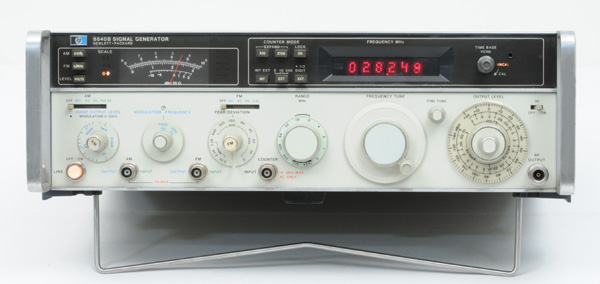 |
| The HP 8640B - CW, AM, FM Signal Generator |
The HP 8640A/B Circuitry
The block diagram of the Model 8640A/B Signal Generator is shown below. HF oscillator always operates in the 230-550 MHz range, allowing use of high-Q cavity resonant circuit. Switched solid-state frequency dividers give the lower ranges down to 450 kHz.
Counter and phase-lock circuits are in Model 8640B only: otherwise Models 8640A and 8640B are identical.
The B version of the Model 8640 can lock its RF output frequency to an internal or external crystal reference, to reduce drift. It also contains a built-in counter that can display output frequency (the counter can also be used to measure external signal frequencies up to 550 MHz).
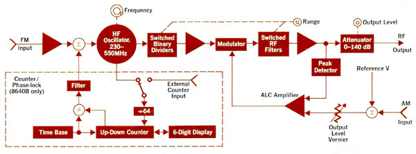 |
The HP 8640 Block Diagram - From the February 1973 issue of the Hewlett Packard Journal
Courtesy of Hewlett-Packard Company |
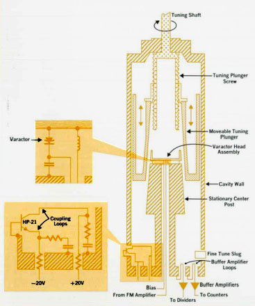 |
The HP 8640 Cavity Master Oscillator
From the February 1973 issue of the Hewlett Packard Journal
Courtesy of Hewlett-Packard Company
|
The Heart of the HP 8640
A coaxial resonant cavity oscillator is the heart of this instrument. The active device is a HP-21 low-noise transistor operating in common-base configuration biased by a current source.
The cavity is less than 1/4 wavelength long so that short at bottom end causes opposite end, near tuning plunger, to appear inductive. Capacitance between tapered tuning plunger and center post resonates with resulting inductance at selected frequency. Moving plunger changes capacitance and thus changes resonating frequency. Varactor diodes are in series with capacitance between varactor end cap and plunger; total capacitance thus formed is in parallel with plunger capacitance.
Feedback for oscillation is by collector and emitter loops coupled magnetically through the cavity. AGC, necessary for stable oscillation, is accomplished by modulating the conduction angle with self bias developed by rectification in the oscillator base-emitter junction.
Animation Display: Panoramic View of the HP 8640B Signal Generator
Animation |
 |
|
|
Use your scrollwheel to zoom in/out
--
Click and drag to view other parts of the image when zoomed |
|
|
|
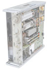
Bottom-Inside View of the 8640B Signal Generator
|
The HP's Hybrid Technology in the Beginning 70s
The Thin-film hybrid-microcircuit power amplifier of the 8640B is located in the upper left corner (Red arrow) of the zoomable photo shown above. The photo below shows this circuit, case opened. It is made by depositing thin-film elements on a sapphire substrate and bonding transistor and diode chips to the film. The technology used chip capacitors, rf transistor amplifier chips, and inductor traces as shown.The substrate overall dimension is 18 x 11 millimeters.
|
Use your scrollwheel to zoom in/out
--
Click and drag to view other parts of the image when zoomed |
|
|
|
Bottom-Inside View of the 8640B Signal Generator
|
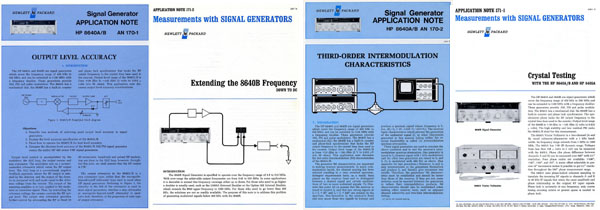
Signal Generator, Dedicated Application Notes
Four application notes dedicated to signal generator measurements were published to help the engineer using the HP 8640. Scans of these original publications are available on the AN page of this web site. Search for AN 170-1, AN 170-2, AN 171-1, and AN 171-2.