The Oscilloscope Product Line Evolution from 1980 to 2000
The Digital Revolution
The 1980 - 1990 decade was a transition period for HP oscilloscopes. It would take those 10 years, to completely change the concept and design of an oscilloscope. There would not be any more Analog Oscilloscopes produced after 1983. That was the year the first "Computer Architecture Based" Oscilloscope, the HP 1980 was added to the general catalog. The 1980 was not yet a Digitizing Oscilloscope, but, it was fully programmable and system oriented, and it opened the door to the design of a new world of fully-digital oscilloscopes.
By the beginning of the 1980s, a 100 MHz bandwidth was standard for Analog Oscilloscopes. The nascent "Digitizing" technology was not yet fast enough to compete with the 100 MHz analog bandwidth, then considered as a major characteristic for a serious laboratory grade oscilloscope. Even with the limited performance of the first generation of Analog to Digital Converters (ADC), a new set of possibilities were added by this crucial component to the task of waveform recording. As the ADC design strategies advanced, this gave birth to a new generation of instruments called "Digitizing Waveform Recorders." The first of them, the HP 5180A, a 20 MHz, 2 Channel, 10 bit ADC resolution was also introduced in 1983. Starting from this performance level, it would still take another 5 years of ADC technology evolution to raise the performance of Digitizing Waveform Recorders into the 250 Megasamples per second range.
With four more creative years of digitizing technology evolution, (sampler circuits, analog-to-digital converters, and digital memories) all the benefits of the Digitizing Waveform Recorders were ready to be integrated into a general purpose Digitizing Oscilloscope. For the first time, in 1992, it was possible to advertise an oscilloscope with this significant slogan "The Feel of Analog, the Power of Digital." With the introduction of the HP 54600 Series, the cost of a 100-MHz digitizing oscilloscope was comparable to a full-featured 100-MHz analog oscilloscope like the HP 1741A. So with that dramatic breakthrough, the HP 1741A became the last Analog Oscilloscope still available in the 1986 general catalog.
The 1990s HP catalogues listed a considerable number of Digitizing Oscilloscope families. The following chapters will browse almost all of them. There is at least one member of each family in the HP Memory Collection.
 |
HP 1745A Oscilloscope
|
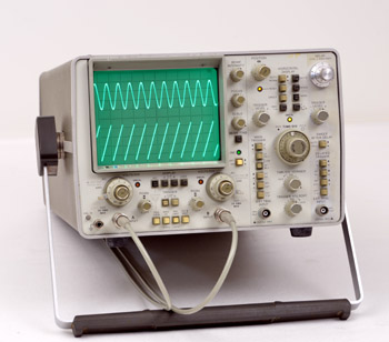
The Last Analog Scopes
The last two analog HP oscilloscopes were introduced in the 1983 catalog.
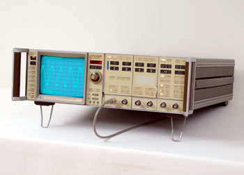
The 1745A was nothing more than a large screen CRT added to the time-tested instrument design of the 1740A family. The new CRT offered a 43 % larger viewing area, while maintaining the original 1740A trace quality.
Voltage measurements were also simplified with a 10 x 10 division CRT graticule instead of the more traditional 8 x 10 division. Full-scale voltage display is ten times the deflection factor, thus greatly reducing the amount of mental arithmetic required of the user when forced to deal with the 8 and 10 number ratio, to calculate percentage.
The HP 1746A, introduced at the same time, added HP's dual-marker delta time capability for faster and more accurate timing measurements. When combined with an optional Digital Voltmeter, a direct digital readout of time interval measurements was featured in a convenient LED display.
All other specification was identical to the original HP 1740A oscilloscope: Both vertical channels provided 1 mV/div deflection factors with DC to 40 MHz bandwidth performance; the full 100 MHz performance was achieved with deflection factors of 5 mV/div to 20 V/div.
The HP 1980 Revolution. Not Yet a Digitizing Oscilloscope,
But Fully Programmable, and System Oriented
The technological innovations integrated into the HP 1980 marked the definitive transition from the analog oscilloscope to the digital oscilloscope. It is significant that the major thrust of these concepts which govern the architecture of today's oscilloscope were invented by the teams who developed the HP 1980. Zvonko Fazarinc was the Product Leader for the development of the HP 1980. Zvonko's team was resident in Barney Oliver's Advanced R&D Lab in Palo Alto. Zvonko's entire HP Memoir is archived on this website. Here are a few of his recollections of the internal events that preceded the development of that instrument:
"It was John Young who came to the lab and asked if we could do something about improving the reputation of HP oscilloscopes that was damaged quite badly by Tektronix's claims that our scopes did not trigger. So Barney Oliver and Paul Stoft gave me the responsibility to come up with some innovative ideas about dealing with the whole issue of the oscilloscopes.
By that time the triggering problems have been fixed by Colorado Springs Division but the bad reputation did not go away. After a few consultations with some of my engineers, we have concluded that the technology of A/D converters has not matured to allow a 100MHz digital oscilloscope which was a goal at that time. But we felt that we have to somehow give the oscilloscope an innovative digital signature of the time.
So we have decided to build an analog oscilloscope whose components would be controlled digitally. This was going to give us a digital self calibration capability and a number of other programmable facilities. We filed for and later obtained a patent on the idea. We were conservative in the sense that we did not want to make a big jump from the conventional external control of the instrument. So our proposal was to replace the existing knobs on the oscilloscope by pushbuttons allowing "Up" and "Down" adjustments with results being visible on a digital display next to the pushbuttons.
We created a mockup of the proposed front panel that we were to show to Barney for approval. But he did not like the idea of so many pushbuttons and displays for each separate function. He wanted just one pair of pushbuttons knob and one display and then a another knob switch with which we were to select the function these two buttons will would control. CS Division and I felt very strongly that it would be too big a jump in concept of an oscilloscope to make such a drastic change. The final argument that convinced Barney of our position was when I told him that "the world is not ready for a one key piano with a pitch selector". This response was suggested by one of my engineers.
So we won and now we were faced with getting the whole thing going. We simulated the major parts of this oscilloscope on the minicomputer and made a demonstration for Bill and Dave and for some selected division managers and their engineers. The demonstration was a success and Bill Hewlett said to the CS Division manager that "he should like the idea". To me he said that he would like to see a prototype in a year. I objected strongly because I knew that we would have to design and build 14 never before tested custom analog/digital integrated circuits to build the instrument.
When I tried to explain to Mr. Hewlett that this is not a pocket calculator, which had only one digital chip, he said with a very friendly voice "Zvonko, if you have something better to work on just let me know" and walked away.
He was a tough customer but has later shown good understanding when the project was very promising but already in the third year. After transfer to CS the acceptance of the new technology has advanced to the point where the divisional engineers adopted Barney's idea about the oscilloscope controls. And many years later the true digital oscilloscope became possible when the technology of A/D converters made more progress."
 |
| The HP 1980B Oscilloscope |
 |
The HP 1980B Oscilloscope
|
The HP 1980B,
Oscilloscope Measurement System
At its introduction, in 1982, the 1980A/B Oscillosope Measurement System was an automated instrument that made significant contributions to the viewing, measuring, and processing of time-domain waveforms.
In its basic configuration, the 1980A/B offered two 100-MHz analog measurement channels with 2-mV/div deflection factors, two independent and direct 5-ns/div sweeps, main or delayed trigger view, delta-time and delta-voltage measurements, and a multitude of automated features including Autoscope, which allowed the user to obtain a display rapidly without adjusting individual controls.
With its HP-IB interface, the 1980A/B could be combined with other HP-IB-compatible instruments to form a completely automated test system. Because the 1980A/B was fully programmable, test routines could be established, stored, and used repeatedly.
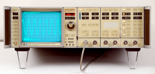
The HP 1980B,
First "Computer Architecture Based" Oscilloscope
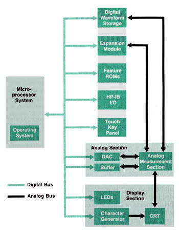
With its microprocessor-based computer architecture, the 1980A/B was a multifunction, multifaceted instrument. Internally, it was divided into eight functional blocks that interface with each other by means of a bus structure.
This extensive digital control permits such features as an easy-to-use front panel, autoranging, complete programmability, digital waveform storage, and hardware and firmware expandability. Unlike other oscilloscopes of the time, the 1980A/B's innovative front panel featured a single rotary control.
Remotely programmed operation was provided through a standard HP-IB port that interfaces with all functional blocks through the internal bus. All measurement parameters can be programmed, and touch key operation, CRT instruction display, and installed-enhancements-addressing are also programmable. Touch key status, measurement results, and digitally stored waveforms may be sent to a computer/controller for processing.
 |
HP 5180A Digitizer with HP 1340A X-Y CRT Display
|
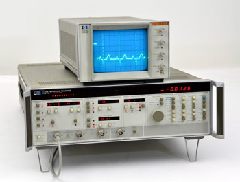
The HP 5180A, First Digitizer
In 1983, at a time when microprocessor computing power was still too slow, and cost of digital memory too high to integrate waveform digitizing and recording inside an affordable standard oscilloscope, a subsidiary solution was alternately offered by HP.
These temporary limitations gave birth to a new generation of instrument called "Digitizing Waveform Recorders." Waveform recorders provide extensive measurement capability, combining important features of storage oscilloscopes and digital voltmeters. They sample analog input waveforms, convert the samples to digital form, and store these digital representations of waveforms in memory. Because they are built around high-speed analog-to-digital converters (ADC's), they capture waveform information in a single-shot manner. (see the HP 5180A Block Diagram below)
A major advantage of waveform recorders is their ability to record information before a trigger occurs. When a waveform recorder is armed for triggering, digitized samples flow into memory. At the time of the trigger, waveform information which is already in memory may be saved; thus, "pre-trigger" recording is possible.
Digital storage of waveform data provides several other advantages. Waveforms can be re-created on a CRT display, or a portion of a waveform may be expanded in the display to show detail. In addition, digitized waveforms can be saved permanently on tape or disk, or processed by digital computer.
The Hewlett-Packard 5180A waveform recorder samples analog signals at a maximum rate of 20 MHz, and converts these samples to digital form. Thus, the 5180A is like a 3-digit voltmeter, taking up to 20 million readings per second, and storing 16 thousand of the resulting digital values in memory.
The 5180A has two high-impedance input channels, A and B, and a third "auxiliary" 50 ohm input channel. Either the A or B channel used alone allows sampling at a maximum 20 MHz rate, or the two channels will alternate sampling in chop mode, with a maximum sampling rate of 5 MHz per channel. The auxiliary channel offers up to 20 MHz sampling rate.
Input voltage range is selectable for the A and B channels independently, between ± 100 mV and ± 10 V. In addition, voltage offset may be added to the input signal. The available offset range is the same as the selected input voltage range. Since it has no input amplifier, the auxiliary channel input voltage range is ± 1 V. This channel inputs directly to the ADC, and consequently has slightly better accuracy than either high impedance channel.
Trigger level in the 5180A is precisely selectable in digital form; a digital readout on the display indicates the currently selected trigger level. In addition, the trigger slope may be rising, falling, or bi-directional. Triggering may be based on the input waveform (internal), or an external trigger source may be supplied.
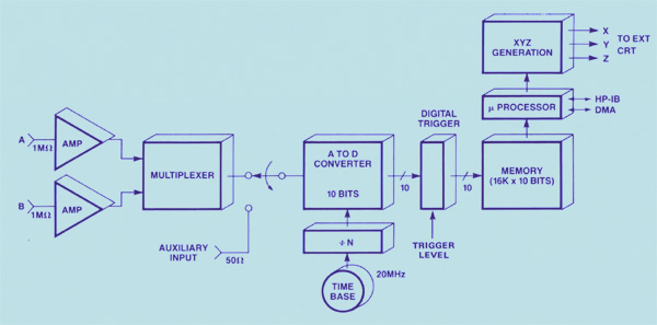 |
| The HP 5180A Block Diagram |
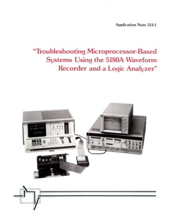
AN-313 Series
As usual at HP, when a completely new technology was introduced, the main concern was: 1) To produce the best possible instrument, making available all the innovation of this technology to the customer. And 2) To publish all the necessary documents which will help the customer to become comfortable in using this new technology. This rule of thumb was particularly true at the introduction of the first digitizer; a never-seen-before technology. The Application Notes in the 313 series were all dedicated to an in-depth knowledge base of the HP 5180A possibilities:
 |
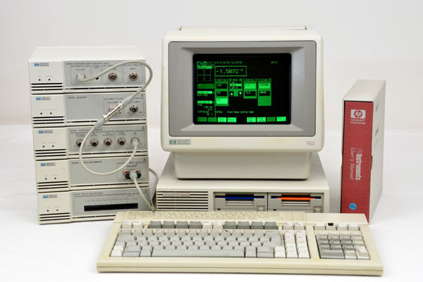
HP 5183T/U Waveform Recorder & Digitizing Oscilloscope Display
|
The HP 5183 & 5185 Waveform Recorders
The rapid evolution of digital circuits during the 1980 decade drove a considerable improvement in performance of the Digitizing Waveform Recorders. Critical to that performance was the Analog to Digital Converter (ADC), and two different ADC design strategies resulted in two different instruments. The 5183A is a 4-megasample-per-second, 12-bit unit, and the 5185A has a 250-megasample-per-second digitizing rate and 8-bit precision.
Paired with an analysis and display module, these two waveform recorders were referenced as HP 5183T/U, and HP 5185T Precision Digitizing Oscilloscopes. They combine analysis functions with high measurement fidelity to characterize single-shot or repetitive signals, either simple waveshapes or complex modulated analog signals.
The measurement strengths of these instruments, coupled with their built-in processing and analysis capabilities, make them well-suited for measurement systems in ATE. production, and R&D environments. In the laboratory, the digitizing oscillocope is a stand-alone, interactive instrument. For many ATE and production systems, on the other hand, the waveform recorder can be used without an analysis display, and IO section to minimize rack space and eliminate front-panel clutter and confusion.
An in-depth description of the design and possiblities of these instruments was done in the February 1988 issue of the Hewlett Packard Journal.
The First Candidates of HP Instruments
Dedicated to HP Personal Computer Control
In 1986, there were already probably close to a million personal computers in the hands of engineers and scientists worldwide, taking advantage of their first generation Personal Computer. With that kind of installed base, it was inevitable that instrument control and automated testing would become available for PCs. And this happened at Hewlett-Packard of course. Pioneer and leader in the field of automated instrumentation and testing, HP was the first to develop a new product line called "PC Instruments". One of the major design objectives was low cost, in keeping with one of the main reasons for the PC's attractiveness. Therefore, the new instruments have no displays, knobs, or controls. Instead, the PC screen displays their front panels and a touchscreen, mouse, or cursor is used to change settings. HP PC instruments come in low-cost plastic packages and when possible, use the computing power of the host PC instead of built-in microprocessors. One interface card plugged into the PC can serve up to eight instruments. Dedicated software was developed to tie instrument control closely to the HP 150 MS-DOS operating system in a first time, and was updated later to make it compatible with the HP Vectra PC, and IBM PC/AT computers.
 |
| The HP 150 "Touchscreen" Personal Computer with HP PCI Instruments and Software |
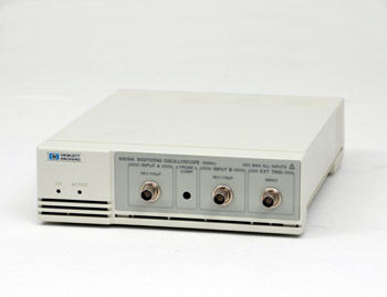 |
The HP 61016A PCI Oscilloscope
|
The HP 61016A, PC Instrument
Digitizing Oscilloscope Module
The HP 61016A module is a medium-performance digitizing oscilloscope designed and manufactured by HP's Colorado Springs Division for the PC Instruments product line. The power and size constraints of the PC Instruments system presented a formidable design task, on the hardware side and software side as well.
Due to the limited power of the host computer of the time, for the hardware, the design was made feasible by using a 6805R3 microcomputer as the heart of the module. This microcomputer contains many of the hardware functions required including an 8-bit analog-to-digital converter (ADC), an 8-bit counter, and a 4-MHz oscillator.
The software for the HP 61016A Digitizing Oscilloscope module was the most complex in the PC Instruments line. The measurement package included control of voltage and time markers and waveform analysis for automatic parametric measurements of rise time, fall time, period, frequency, pulse width, overshoot, preshoot, and peak-to-peak voltage. The HP 19800 Waveform Measurement Library, which were developed for the HP 1980 Oscilloscope, laid the ground work for the measurement package algorithms. The HP 19800 Library was written in BASIC for the HP 1980 Oscilloscope and was converted to C for the HP 61016A.
The resulting specifications of a 61016A PCI Oscilloscope connected to a HP 150 computer, can be resumed as follow:
- Vertical Bandwidth: DC to 50 MHz
- Vertical Range: 40 mV to 40 V, full scale
- Vertical Sensitivity: 5 mV/div to 5 V/div, in 1-2-5 steps
- Timebase Range: 100 ns to 5 seconds, full scale
- Sweep speed: 10 ns/div to 500 ms/div, in 1-2-5 steps
- Digitizer A/D Resolution: 8 bits
- Automated Measurements for: Frequency, Period, Risetime, Falltime, + Width, -Width, P-P Volts, Preshoot, and Overshoot.
- Autoscale Feature displays: both channels with the proper vertical, trigger, and timebase setting.
The HP Modular Measurement System. Another Family Including Digitizer
The first elements of the HP Modular Measurement System (MMS) were introduced in 1986. Hosted by the Santa Rosa division and called the “Redwood Project," their goal was to propose a next generation high frequency instrument concept that would utilize generic building blocks/modules and main frames developed by the various participating HP divisions. This allowed the designers to add incremental capability or frequency range when the technology became available. By building the necessary microwave components into a compatible plug-in, the mainframe did not have to be redesigned for each added new capability.
Hugo Vifian was the leader of the "Redwood Project" at Santa Rosa. An in-depth description of the MMS concept can be found inside Hugo's story which is on line on this website.
Mostly composed of Spectrum Analyzer Building-blocks at the beginning, the HP 70700A, 20-Msample/s, 10-bit programmable Digitizer, including a full set of oscilloscope features, was introduced in 1988.
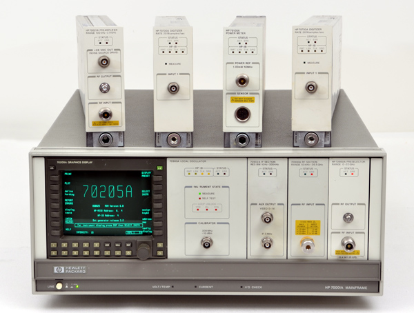 |
| The HP Modular Measurement System (MMS) with a few Plug-ins |
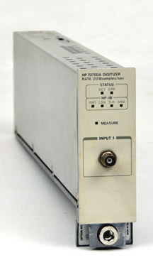 |
HP 70700A Digitizer
|
The HP 70700A Digitizer
The HP 70700A digitizer adds precision digitizing capability to the modular measurement system. The 1/8-rack-width module has all features of a 20-Msample/s, 10-bit programmable waveform recorder, plus more including a full set of oscilloscope features, and memory size of 256k samples.
Built-in oscilloscope features include:
• Menu-driven user interface
• Auto-scale
• Pre-trigger data
• FFT
• Time and voltage markers
• Split timebase mode
• 256K sample memory
• Trace averaging
• Automatic pulse parameter measurements
• Waveform math functions (add, subtract, and multiply waveforms)
• Multi-channel capability (control up to four channels/modules from the menu)
The digitizer module can function as a self-contained instrument with comprehensive data-acquisition and waveform analysis capabilities. The module can be used as a precision digitizing oscilloscope, a transient analyzer, or a programmable waveform recorder. In multichannel applications, up to eight HP 70700A modules plug into a 70001 mainframe can be operated synchronously without loss in performance.
Integrated into an HP 70000 modular spectrum analyzer, the digitizer module improves the system's ability to analyze signals in the time domain. (See picture below)
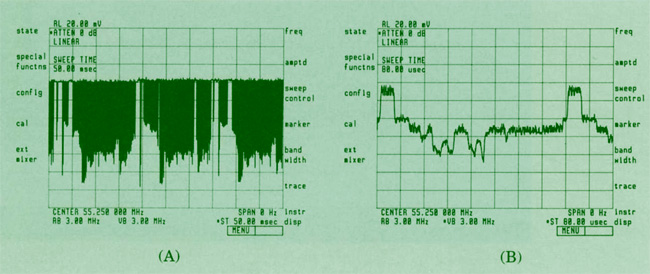 |
(A) Spectrum analyzer performance in zero span without the digitizer.
(B) Adding the digitizer improves the spectrum analyzer's ability to recover modulation. |
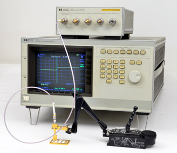 |
HP 54120T Digitizing Oscilloscope
with HP 54121A Four Channel 20 GHz Test Set,
and Agilent N1020A TDR Probe
|
The HP 54100 Series
Starting with the HP 54100A in 1985, the 54100 series of digitizing oscilloscopes will grow, adding one or two new models to the series, each year, until 1990. The 54100A was described in the April 1986 issue of the Hewlett Packard Journal.
To the first HP 54100A, 1GHz bandwidth, 350 ps rise time, the 1986 catalog added the 54110D, a color screen version with extensive logic triggering.
In 1987, the 54111D was introduced with an extended memory of 8 k per channel, and all the necessary features for controlling and managing the added memory depth, such as scroll, zoom, and memory bar.
In 1988, one more memory extension gave birth to the HP 54112D, a "Four Channel 64 k Deep Memory Oscilloscope," and Quad megasamples per second digitizers.
Also introduced in 1988, the HP 54120T, with its companion HP 54121A, four channel 20 GHz Test Set, (picture above) was the fastest oscilloscope ever produced by HP. With 0.25 ps time interval resolution, 10 ps time interval accuracy, and a 35 ps step generator integrated in the 54121A test set, the 54120T also combine a fully calibrated Time Domain Reflectometer with the 20 GHz bandwidth oscilloscope.
In 1989, true triggering to 18 GHz was added to the 54120T using the new 54118A Trigger Input.
In 1990, the series was enlarged with 3 new configurations offering a choice of bandwidth: The 54122T with 12.4 Ghz bandwidth and 28.2 ps risetime; the 54121T with 20 GHz and 17.5 ps risetime; and The 54123T with 34 Ghz bandwidth and 10.3 ps risetime.
And finally in 1991, a last model in the series, the HP 54124T enlarged even more the bandwidth up to 50 GHz, and reduced the risetime to 7 ps.
By the Way, What About Probing ?
As we list and describe all the oscilloscopes and digitizers produced by Hewlett Packard on a 20 year timeline, it's impossible to ignore an accessory common to all these instruments, and important to the final accuracy of their measurement.
Selecting the right probe for a particular measurement involves many choices. When an oscilloscope measurement is made, the circuit under test is disturbed since energy must be transferred from the circuit to the oscilloscope input. Effectively, this means that what is being measured is not just the circuit under test, but the combination of the probe, oscilloscope AND the circuit under test. The idea then, is to select a probe that will affect the test circuit the least and still have the necessary characteristics to make the measurement of choice with accuracy. These considerations are hardly a trivial matter on digital waveforms that act much like microwave signals, with all that inherent transmission line technology.
Another major problem is the probe physical design. With a continually growing variety of electronic components, and their continued miniaturization, oscilloscope probe design became another brainstorming subject for the innovative HP engineers.
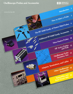
Some excerpts of an Oscilloscope Probes and Accessories catalog published in 1988 have been compiled in the PDF document presented here. They give: 1) A recap of the fundamentals to answer the question "How to Select a Probe," and 2) An exhaustive listing of all the probes and accessories available at HP in 1988, to solve the delicate problem of oscilloscope probing.
Click here for a PDF of the 1988 Oscilloscope Probes and Accessories Catalog - PDF 2 Mb
 |
HP 54503A Digitizing Oscilloscope
|
The HP 54500 Series, General Purpose Digitizing Oscilloscopes
By the beginning of the 1990s it was possible to take advantage of all the recent technologies developed for the waveform recorders and digitizers to design a more general purpose oscilloscope.
The HP 54501A was the first of the general-purpose, benchtop series introduced in 1989. With four channels, 100 MHz bandwidth, dual timebase windowing, fully programmable, and 16 automatic pulse parameter measurements, it was introduced at a $3,465 list price.
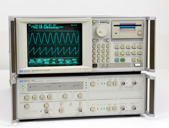
One year later, in 1990, two new members were added to the family: The HP 54502A, a 400 MHz repetitive signal / 100 MHz single-shoot bandwidth model, and the 54503A, a 500 MHz 4-channel model. (picture above).
In 1991 the 54504A added a 400 MHz 2-channel, 200 Msample/s model to the series, and using HP's custom ADC design, the 54510A boosted single-shoot performance to 250 MHz by introducing the first 1 Gigasample-per-second portable oscilloscope.
 |
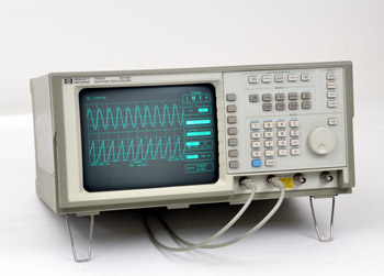
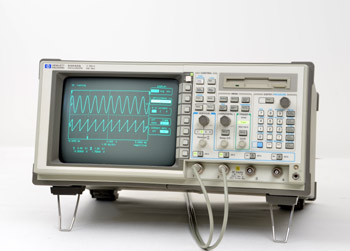
HP 54600A Oscilloscope
|
The HP 54600A,
Feel of Analog . . .
. . . Power of Digital !
The HP 54600A two-channel, and HP 54601A four-channel, 100 MHz Oscilloscopes were both introduced in the 1992 catalog. The impact of the innovations featured in these low-cost oscilloscopes were such that they were the subject of a 54-page article in the February 1992 issue of the Hewlett Packard Journal.
As digitizing technology (sampler circuits, analog-to-digital converters, and digital memories) had steadily improved, the cost of digitizing oscilloscopes decreased. For the first time, with the introduction of the HP 54600 Series, the cost of a 100-MHz digitizing oscilloscope was comparable to a full-featured 100-MHz analog oscilloscope.
The two oscilloscopes are identical in capability except for the number of channels.Both oscilloscopes have two full-range inputs (2 mV/div to 5V/div). In addition, the HP 54601A has two limited-attenuation inputs (100 mV/div and 500 mV/div) optimized for use with logic signals, while the HP 54600A has an external trigger input. The bandwidth of all channels is 100 MHz. A maximum sample rate of 20 megasamples per second provides a 2-MHz bandwidth for capturing singleshot events. The 8-bit analog-to-digital converter has a vertical resolution of 0.4%.
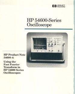
Among the number of innovations, the fast Fourier transform algorithms (FFT) to convert a digital time-domain waveform to a discrete frequency-domain representation, was one never seen before on oscilloscope of this low price level. The HP 54600-4 Product Note, reproduced below, provides a brief review of Fourier theory, and gives some typical application examples.
Using the Fast Fourier Transform in HP 54600 Series Oscilloscopes
The HP 54600 series of oscilloscopes with the HP 54657A or HP 54658A Measurement/Storage Module installed have the ability to perform frequency domain analysis on a time domain waveform using the internal Fast Fourier Transform (FFT). This product note provides a brief review of Fourier theory, especially the unique behavior of the FFT. The note also describes how the HP 54600 FFT works, gives some typical applications and provides some tips on how to get the most out of the FFT capability.
The link below gives access to a copy of the 30 page original product note.
PDF format (2.8 Mb)
Using the Fast Fourier Transform in HP 54600 Series Oscilloscopes
 |
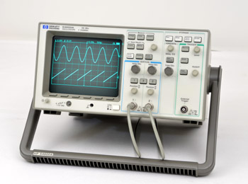
HP 54542A Oscilloscope
|
Another Extension of the 54500 Family
In 1994 four new members were added to the 54500 family. The 54520A, 54522A, 54540A, and 54542A feature a new user interface with dedicated vertical, horizontal, and trigger knobs. They have maximum sample rates from 500 MSa/s to 2 GSa/s, and offer features to make testing easier, including an MS-DOS compatible disk drive to store waveforms or instrument setups.
Like every other digitizing oscilloscopes of the 54500 Series, these new members offer features such as autoscale, pushbutton hard copy, automatic measurements, nonvolatile setup and waveform memories, and full HP-IB programmability.
The HP 54542A, most sophisticated unit of the 9 different models in the 54500 Series, is shown above. It is a four-channel, 2 GSa/s maximum sample rate, and 8 bits resolution with 32 k real time record length. The vertical sensitivity goes from 1 mV/div to 5 V/div, with a maximum input of ± 250 V at 1 MΩ input impedance, or 5 V rms at 50Ω. The timebase range is 500 ps/div to 5 s/div. The FFT visualization, which is standard on all four models, is specified to 1 GHz on the 54542A.
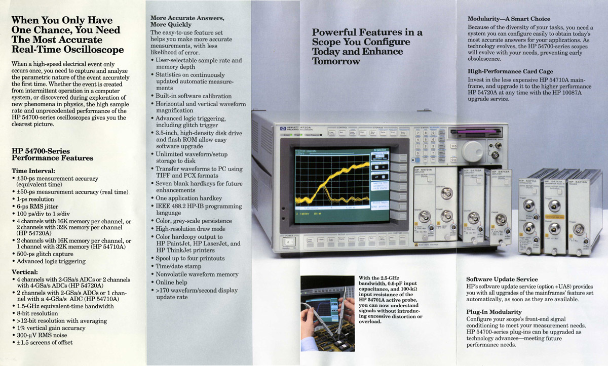
Another Step Ahead with the HP 54700 Series
The first two members of the 54700 family were introduced in the 1993 catalog. To enlarge the different configurations the hardware design of this new series went back to an old but efficient concept: a Mainframe and a Collection of Plug-ins. The first two mainframes of this new modular design family were the HP 54710A, and HP 54720A. Depending on a choice of plug-ins, introduced at the same time, the overall performance of a 54700 can go up to 4 GSa/s sampling rate on two channels, 50 ps time interval accuracy in real time mode, or 1.5 GHz bandwidth in equivalent time mode. Specific short-form specifications as a function of the plug-ins installed in a 54710A or 54720A mainframe are summarized in the table below. Overall characteristics can be read from the copy of a commercial document you can pop-up by clicking the picture just below.
In 1995, the performance was one more time increased considerably with the introduction of the 54750A mainframe, and HP 54751A 2 channel 20 GHz Plug-in. The quantity of plug-ins compatible with the 54750A mainframe increased at about a 1 per year pace up to 1999. The final collection included a 2-channel 20 GHz oscilloscope with single-ended TDR (54753A), and a 2-channel 18 GHz unit with differential TDR module (54754A).
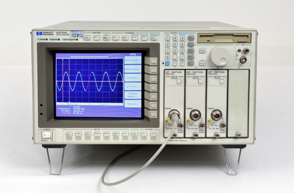 |
 HP 54710/720, advertising flyer June, 1992
HP Memory Collection |
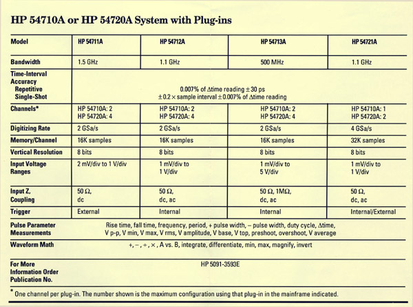 |
| Short-form specifications as a function of the Plug-ins installed in a 54710A or 54720A Mainframe |
Close-up View of the 2 Gsa/s Acquisition Hybrid Circuit Developed for the HP 54710A & 54720A Digitizing Oscilloscopes (Zoomable)
The original hybrid circuit size is 90 mm wide X 80 mm high.
|
Use your scrollwheel to zoom in/out
--
Click and drag to view other parts of the image when zoomed |
|
|
|
HP's 54710A/54720A 2 Giga-Sample/second Acquisition Hybrid |
VXIbus, a New Test and Measurement Standard
Developed by Hewlett-Packard in the mid-1970's, the IEEE488 (HP-IB) interface allows easy connection between instruments and a remote computer. In the late 1980's, Hewlett-Packard offered a standard instrument language that was quickly adopted by the Test and Measurement industry as SCPI (Standard Commands for Programmable Instrumentation).
During this time, HP and other instrument manufacturers produced a growing number of proprietary HP-IB modular instrument products. These instruments could be integrated into test systems to provide switching, measurements and signal source capabilities. However few of these modular products were compatible. The VXIbus standard addressed this problem of incompatibility. With the success of the VXIbus standard, other standards - like VXlplug&play and SCPI - emerged to improve the usefulness of VXIbus technology in electronics test.
On a hardware point of view, the VXI standard introduced the concept of cardcage and IAC (Instrument-On-A-Card) systems.
It is not the purpose of this chapter to develop the VXI concept any more. But among the hundreds of "Instrument-On-A-Card," to be plugged in a VXI mainframe, and listed in the HP catalog by the end of the 1990s, a lot of them were Digitizer, Oscilloscope, and Waveform Recorder. The E1428A described below was one of them, very similar to a General Purpose Oscilloscope.
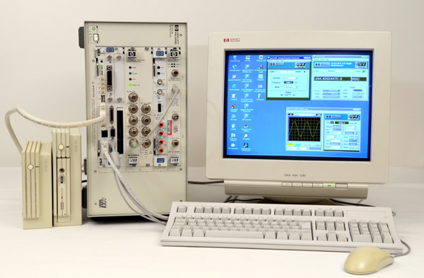 |
| HP VXI C-size Mainframe with E1428A 1 Giga sample/s, 250 MHz Oscilloscope |
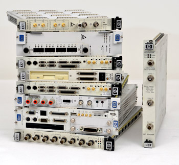 |
A Stack of VXI Modules - HP E1428A on the right
|
HP E1428A, 1 GSa/s,
VXI "Oscilloscope-On-A-Card"
The HP E1428A Digitizing Oscilloscope is a C-size, 1-slot, message-based VXI module. It has two channels with each channel containing an 8-bit A/D, and 8,000 point memory to simultaneously capture at up to 1 GSa/s. It is similar to a 54510A bench oscilloscope in its specifications and its programming language as well.
For fast capture of many waveforms, the HP E1428A offers sequential single-shot mode which internally stores successive waveforms rapidly. The memory can be optimized for acquisition speed or capacity. There are 100 K-words of internal RAM or 500 K-words of shared RAM for segment storage.
The HP E1428A comes with both the SCPI command set and an HP 54510A-compatible command set. The compatible language provides a use model where programs can be developed using the HP 54510A bench oscilloscope. Using the HP 54510A provides direct visual feedback to the programmer during program development. Once programs have been developed on the HP 54510A, they can be run on the HP E1428A with only minor modifications.
The SCPI language is available for users who are more familiar with SCPI. But not all of the complex triggering capabilities of the HP 54510A and HP E1428A are implemented in the SCPI language.
The picture below is a screen dump of the software panel driver of the E1428A Oscilloscope. It shows that every necessary control to operate the oscilloscope is "Mouse-click" available on the computer screen, and that the resulting waveform can be display while the test is running on the remote oscilloscope.
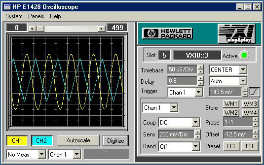 |
| HP VXI E1428A Oscilloscope Panel Driver |
HP "Infiniium," A New Family For A New Century
The first members of the HP 54800 Series, "Infiniium" Oscilloscopes were introduced in 1998. They would capture the title of "The Scopes of the Beginning 21st Century," making the transition from a Hewlett Packard product line to an Agilent one. The Infiniium series was the first to combine a simple, analog-like front panel, the graphical interface of a Personal Computer, and a built-in information system.
The first members of the HP 54800 family featured a number of five models, with bandwidth from 500 MHz to 1.5 GHz, sample rates up to 8 GSa/s, and 2 or 4 channel models. They all have LAN connectivity, and internal Hard and Floppy Disk Drives to store screen images as BMP, EPS, GIF, TIFF, or PCX file formats, for easy import into various programs for documentation or further analysis.
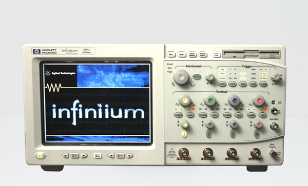 |
| HP 54820A one among the large family of HP Infiniium oscilloscopes |