

One of our main objectives in starting this website five years ago was (and still is today) to get in touch with people who have worked at HP from the birth of the company up to today. We are interested in hearing your memories no matter what division or country you worked in, or whether you were in engineering, marketing, finance, administration, or worked in a factory. This is because all of you have contributed to the story of this unique and successful enterprise.
Your memories are a treasure for this website. While product and technology are our main concern, other writings related to the company life are highly welcome, as far as they stay inside the HP Way guidelines.
The contributions made by Edward H. Phillips during his career at HP are illustrated in this chapter. This chapter is a good example of the type of memories we would like to present on this website.
Many thanks Ed for this highly valuable contribution.
Anybody Else ? Please get in touch using the Contact US form.
Actually, my family connection with Palo Alto goes back to 1907 when my maternal grandparents moved there with a newborn child (my mother). My grandfather had been an accountant back in Michigan and had briefly worked as a bookkeeper for Henry Ford when he occupied a rented building (i.e., such as you can see today at Greenfield Village in Dearborn). This was a long time before the Silicon Valley came to be of course, and confronted with a lack of any requirement for accountants my grandfather became a self-taught architect and contractor. This was because Mrs. Stanford was bringing in a number of professors from the East and they needed places to live. You can still see the old pre-WWI homes that he built along Embarcadero Road for a few blocks East of Alma Street. But a few years later, he ran out of newly minted Stanford professors and so the young family moved to the East Bay.
One reason that this may be of interest is that they sold their own home to Lee De Forrest, the inventor of the Audion (the first working vacuum tube). Another reason is that this led to my being raised in wartime Richmond where during WWII Henry Kaiser built about 1,000 ships in Shipyards 1 & 2 (with 20 ways between them). Richmond, as a city of about 23,000 in 1940, wasn't really ready for accommodating about 100,000 ship building workers over the next five years so anyone that "was warm to the touch" was "drafted" and put to work doing something.
My grandfather managed the building and then administration of temporary housing for about 30,000 people while my mother went back to teaching (my stepfather already had a job as the controller of the Sir Francis Drake Hotel in San Francisco). The main problem however, was that initially there wasn't any time to build schools. Would you believe shifts - how about four shifts per day in elementary school class rooms shared by two teachers with each class being about 90 students in size! This was before busing so I escaped that because we lived on the opposite side of town. But my mother (equipped with a "B" gas ration card) commuted to her school every day where during each afternoon she taught about 180 students in two shifts. There were 5 rows of 8 desks, or 40 total. The kids sat two to a desk (or three if they were small enough) - and those that were left over stood at the blackboard!
Following my graduation from Richmond High in 1950, I entered UC Berkeley majoring in Engineering Physics - just about at the beginning of the Korean War. This led to a lot of us signing up for ROTC and committing to 24 months of active duty following graduation. That allowed us to finish school before entering the Army. This part of my story is pertinent to my hp memories because, while UC Berkeley was (and is) one of the top engineering schools in the World, it (along with any other school I ever heard of) provided absolutely no educational experience that prepares one for becoming a mechanical design engineer (more about this as we go along because interviewing prospective ME's was to be part of my job at hp ).
In any case, in 1956 my favorite US President, Dwight D. Eisenhower, decided to let us out three months early in an effort to balance the budget. Thus while still in the army (e.g., on leave), I found myself back in Richmond in April 1956 - with a new wife that I had brought back from Germany. Needing a job, I asked my uncle who had been sales manager and was at that time plant manager of American Brass & Copper in Emeryville (and knew everybody in the Bay Area) where I should apply for work as a mechanical engineer. Without batting an eyelash he said "Hewlett Packard". To which I replied "What's a Hewlett Packard?". He wasn't really sure - but he was darned sure that it was the best company in the Bay Area !
So the next day I drove down to Palo Alto and found hp at 275 Page Mill Road. I simply walked in and suggested to the receptionist that I would like to apply for a job (i.e., at the tender age of 24 I had never done that before as must be obvious)! So the conversation then went something like "Really, as what?". "As a Mechanical Engineer." "Does anyone know that you are coming - do you have an appointment?" "No, do I need one?" Well by then it was about a quarter to 12:00 so she said "Come back after lunch - I'll see what I can do." By then I began to realize that had made errors in my approach toward actually getting a job. But I thanked her and went off to find a hamburger - and came back at 1:00 hoping for the best.
Much to my relief, a few people (including Ralph Lee and Bruce Wholey) did interview me that afternoon. As it turned out, hp had purchased the microwave line of instrumentation from Varian a few years earlier and were anticipating extending the line upwards in frequency into the K and R bands. It is an absolute fact however, that until that very moment - I had absolutely no idea what a mechanical design engineer was nor the faintest concept of how he or she performed his or her job! Nothing in my schooling, high school or university, and certainly nothing in the army had prepared me for this opportunity - but there must have been something in my eyes that indicated a grasp of what might be required because about two days later a very generous job offer came in the mail.
I couldn't get to the telephone to accept fast enough! I was invited to return to Palo Alto to discuss practical things like filling out the necessary paperwork and getting a more detailed explanation of what I was going to be doing - along with some idea of where I might live. I next proceeded to buy a tract house (on the GI Bill) and bought furniture and appliances from a government wholesale outlet in San Francisco (I was still in the Army) - and then went off to Fort Ord for a week to actually become separated from the US Army (e.g., on May 9, 1956).
During the following week I rented a truck, picked up the furniture, and moved into the house on Diablo Ave. in Mountain View - which as a side story is notable because one of our neighbors was the Jobs family with young Steve being a very young child at the time - and perhaps even more notable because eight years later Steve's father was trying his hand at selling real estate. The first house that he listed and the first that he sold (e.g., within two weeks!) was ours. Anyway, back in 1956 everything was pretty well buttoned down by May 15th and I started work at the old hp plant at 275 Page Mill Road on May 16, 1956.
The first thing that happened to a new engineer was that he or she spent considerable time out in the plant learning something about actually producing instruments. Electronic Engineers (hereinafter "EE's") spent six months out there with most of the time as test engineers - while Mechanical Engineers (hereinafter "ME's") spent three months with the first two months involved in doing most of the assembly jobs, a little plastic molding and some machining, and the third month trying their hands in a somewhat limited fashion as test engineers.
There were lighter moments of course. I remember a picnic to which we new engineers were invited. I can remember Tom Lauhon ( hp 's second Industrial Designer), Frank Ura (soon to become our resident expert in vacuum deposited films) and Lee Bodily (who later gained fame as the engineer that flew around the world with an Atomic Clock to finally prove Einstein's theory relating to time being a function of speed correct) being there. And then of course there was the occasional beer bust!
In any case, when a new ME had finished his period of factory acclimation, he or she reported to Don Borthwick and Ralph Lee - and in essence became the manufacturing engineer for the whole company. As such you ran around "putting out a lot of fires", and in the process were exposed to pretty much of everything relating to the company and really learned how it ran.
That started with a 17 week schedule generated by the marketing department. The 17 week schedule went to the husband and wife production control team of Keith and Mary Elledge. They knew what our stock situation was via an elaborate Kardex system - and caused orders to smoothly go to purchasing as well as to the shop and assembly areas on the basis of established lead times. Everything went pretty much like clockwork with very few back orders and little assembly line down time. In order to make all of that possible, material lists and Kardex cards all had to be correct - so creating them was a major responsibility of any project's ME. And of course, if the manufacturing engineer (e.g., in my time at that job - me) ever did anything that required modification of any of those items. He (that is I) was responsible for keeping everything moving smoothly and everyone that needed to know informed - and as I remember often getting Don Borthwick's approval.
But what was the general nature of the "fires" that needed putting out you ask? Well, they usually related to things that simply didn't fit - even though a particular instrument had been in production for some time. This often happened because different machinists made critical parts of an assembly, and even though parts made by any of the machinists were within tolerance - they all of a sudden wouldn't work together.
How can this be? It falls back on the responsible ME who did the part design and tolerancing in the first place. As I was later to find out, in high volume manufacturing (e.g., think auto manufacturing) they generally have a "book" on each part that includes an assembly tolerance "stack" drawing. The salient features of such "stack" drawings are the critical dimensions that govern an assembly's assemble-ability. For instance, if a part mounts in against a shoulder facing one way and in turn mounts a ball bearing against an internal shoulder facing the other, the axial distance between those shoulders is such a critical dimension. Thus if the responsible ME had dimensioned the part such that he or she "went around Robin's barn" to finally generate that axial dimension, then a tolerance buildup would occur and show up on the "stack" drawing. Then that would have been corrected by directly dimensioning the critical distance. This would have been followed by a tool engineer processing the part such that both surfaces were machined in the same set up.
Up until then however, no such procedure existed at hp. As a result, I ran into all sorts of what really amounted to fundamental dimensioning philosophy errors that had to be corrected. This often required rework or even replacement decisions. And this in turn might involve Kardex entry and part and/or material ordering issues (i.e., I got to know Keith and Mary Elledge quite well!). One small and seemingly quite simple instrument that I very well remember in this regard was the 476A Universal Bolometer Mount. This is because its dimensioning philosophy was really quite backward, and for the first time required me to make an informal "stack" drawing before re-dimensioning its critical parts.
It happened that the pilot runs of the then new 626A/628A Signal Generators ran into serious trouble during the Fall of 1956. Priced at $3,250, they were by about $500 the most expensive instruments in the line at that time. Or putting it another way, those deadlined pilot runs represented about $65,000 of sales out of somewhere just north of $25 million for the whole company that year. Or putting it yet another way, there was a lot of pressure on Larry LaBarre, the project's lead ME!
The problem was that there was a failure in the frequency drive mechanism used for tuning the klystron cavity. Specifically, the drive and anti-backlash mechanism therefor consisted of a slotted scroll-type cam with a yoke mounted pair of small ball bearings - one in direct rolling contact with one shoulder of the slot and the other mounting a (larger diameter) "tire" comprising inner and outer steel bands separated by perhaps 1/8th inch of molded low durometer rubber - resulting in the outer steel band then being compliantly loaded against the opposite shoulder of the slot. The failure mode? The bond between the inner steel band and molded rubber was failing on all 20 of the cam drives!
I suggested modifying the assembly such that three thin section ball bearings could be placed side-by-side on a sleeve with the center one having a larger inside diameter and being eccentrically positioned on an eccentric lobe of the sleeve. Then the sleeve was to be spring loaded (e.g., rotationally about the 1/8th shaft upon which it was mounted) such that the eccentrically mounted ball bearing forced the other two against the inside shoulder of a slightly modified cam.
Larry asked me to draw it up and get a prototype made ASAP. I did, and it worked fantastically well! Larry was very grateful and even went out of his way from then on to unofficially mentor me. But the only other observation that we heard was from Ralph Lee who turned my solution down flat because it added something like $10 (mostly in the form of more expensive ball bearings) to the cost of the instruments.
This led to me redesigning the assembly so that it could use three relatively cheap 1/4 x 5/8 ball bearings at the cost of slightly more machining cost involving some clearance machining on the supporting casting and an additional small sleeve so that the outside ball bearing could be assembled last on a smaller diameter portion of the spring-loaded sleeve. My memory is that outside of a tapped hole in the supporting casting for mounting the other end of the spring, no other modifications to either instrument were required. And so finally the pilot runs proceeded and the instruments were released for production (that lasted for more than 20 years because the 626A and 628A are still offered for sale in my 1977 catalog).
Then during the Winter of 1956/57 something really quite unusual happened. One day a newly hired fellow named Jack Riddle came by and introduced himself while leaning over my drafting table. Mr. Packard had just hired him away from a rising position in the management chain at Ford. Apparently, Jack's first assignment was to investigate various circumstances relating to establishing the first overseas manufacturing plant in Germany. In order to be able to familiarize himself with Germany, Jack's apparent first action was to find out whether anyone in hp 's cadre of salaried employees had spent any significant post-war time in Germany. I guess that since I was only about eight or nine months removed from having served in the Army in Germany (for 16 months), he had decided that I was the one to talk to.
The first thing I asked after he explained his mission, was where did they anticipate locating the plant? He answered "Oh, I don't know. We thought maybe somewhere near Munich." - to which I replied "I wouldn't do that.". Jack was surprised by that observation and asked me why, to which I replied something like "Well, besides more paid holidays there, I think that you'll find a stronger work ethic further west - generally in the Stuttgart area.". (And since I had lived in both areas I could fill him in with some detail.)
I have no idea whether the above had anything to do with the plant eventually being located in Böblingen, but roughly a year later Ray Demere started sending back little notes from Böblingen (that appeared in Watt's Current) relating to difficulties involved in living in early postwar Germany - for instance, things such as doing the laundry in the bathroom tub and hanging it about the apartment to dry! (That I couldn't understand, because in the BOQ's we always had a maid who took one's laundry at the end of each week and delivered it washed and neatly packaged on Monday with a bill for about 8 to 12 Marks ($2 to $3) - not to mention that every married Chief Warrant Officer or Officer above the rank of First Lieutenant seemed to have a maid (at about $50/month).
Until 1957, ME's were located in a portion of the open administrative space as opposed to being in the laboratory with the EE's. This meant that there was a somewhat compromised team effort in getting out any new instrument. In fact, the common expression used for communication between EE's and ME's ostensibly working on a given project was "throwing a breadboard or design concept over the wall" (e.g., in either direction). But that all changed in early 1957 (February I think) with the first hint of divisionalized organization. Production engineering became its own profession whereby I was the last "temporary manufacturing engineer for the whole company" and finally became a full-fledged ME. The newly minted "professional" manufacturing engineers and the tool engineers were left in the open administrative space while we ME's moved into the lab.
The laboratory was about 48 feet wide (e.g., able to accommodate five columns of side-by-side 8-foot long EE workbenches plus two 4-foot isles) by perhaps a little more than twice that in length. That left room at the back of the lab for three four table arrays of back-to-back 5-foot drafting tables (e.g., with the four drafting tables each oriented parallel to the EE's workbenches) with a single four drawer filing cabinet positioned between each pair of facing drafting tables (fortunately, I don't remember any left handed drafting arms!). Each ME also had a 6-foot long workbench separated from his or her drafting table by at least a 4-foot space. All of that plus a 4-foot laterally running isle that separated us from the EE's resulted in us occupying the back 24 feet or so of the lab. That left room for perhaps eight rows of EE's in the front of us for a total of perhaps 56 individuals (e.g., although all of the available positions (especially in the ME section) weren't occupied). Amongst the group there were a couple of technicians and three of the ME positions were occupied by Carl Clement's burgeoning industrial design group (it became a group of three very soon with the addition of Al Inhelder).
There was a management shift as well. We no longer reported to Ralph Lee. In fact my new boss was Bill Myers. I want to especially mention Bill because he never seems to be mentioned in historical writings about hp . Yet Bill was very important to hp during the very important period spanning the early to mid 1950's as the company became the dominant producer of electronic instrumentation. During that period hp won all of a series of government contracts for developing high frequency signal generators and Bill was the responsible EE on most of the resulting projects. I believe that either he was, or that he along with Art Fong, were the development EE or EE's on the 614A, 616A, 618A, 620A, 626A and 628A signal generators. I only remember receiving one bit of advice from Bill: "When it came time to begin work on a new signal generator, the first thing I did was to walk up and down the aisles of the stock room to see if there was anything there that I could use again." That was it! In point of fact, working under Bill was a real pleasure because he operated on the principle of "If it ain't broke, don't fix it!", wherein I was allowed to create and design things without much if any impedance!
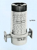 |
At first I designed simple stuff like the K & R band 370 Fixed Attenuators, 375 Variable Attenuators, and 752 Directional Couplers. With the exception of considerable help from Frank Barnett on the 752's (see further discussion below) these projects were just simple scaling (e.g., making them smaller) and paperwork jobs (e.g., material lists and Kardex cards) requiring little if any creative design. But then somewhere toward the middle of the year I finally got permission to design the P, K and R 532A Frequency Meters (i.e., a catalog picture of a P532A is shown at the left) as well as the K & R 382A Precision Variable Attenuators (i.e., a catalog picture of an R382A and a generally descriptive schematic picture thereof are shown hereinbelow next to a story about them).
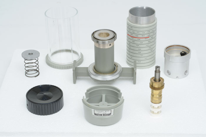
It occurs to me that many readers may not know what a 532 Frequency Meter is - so with the aid of the elaborate disassembled view below provided by Marc Mislanghe, let me try to explain. The round polished bore in the cylindrically shaped object (hereinafter "cavity tube") that extends vertically from the waveguide is of course the instrument's cavity bore. As can be seen via the rectangular cutouts in the molded nylon base, the cavity tube is laterally displaced with respect to the waveguide's center. Thus a small oblong shaped opening formed at the edge of the waveguide (not shown but in the center of the bottom of the cavity) provides a path for small coupling currents to pass into its center when the leadscrew/plunger assembly shown at the lower right portion of the picture is tuned such that the cavity is resonant at the frequency passing through the waveguide (i.e., the currents in a waveguide run on the surfaces thereof while the electric field has its maximum value at the center of the waveguide).
 |
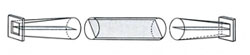
| Click in Picture to See Animation |
The power so transmitted during resonance is lost and thus results in a small (e.g. 1.5 db) dip at a downstream detector as either the frequency is swept, or the cavity height altered. The silver-rhodium plated, non-contacting plunger has a series of nominal quarter-wave length long low impedance sections (three each) and high impedance sections (two each) - the idea being that the entrance to each low impedance section looks like a better short because a quarter wave-length away there is a high impedance transition that looks like an open circuit and so on. The plunger shown is typical of the P, K and R 532A Frequency Meters but not the larger G, J, H and X 532's (i.e., see a story about the G, J and, H 532's below) because they had two folded high impedance quarter-wave sections in order to minimize overall cavity height.
Actual construction details of the waveguide/cavity structure varied between the X, P, K and R 532's and the G, J and, H 532's as well because the smaller ones had soldered (together) waveguide and cavity tube portions while the larger ones used an aluminum casting with a large diameter bore to a shoulder just coincident with the upper inside surface of the (broached) rectangular waveguide sections at either end. Then a cavity formed from a soldered together cavity tube and bottom plate portions was fastened onto the bottom casting.
As far as the 532 project goes however, please notice that the above initial list didn't include an X532A. That is because there was an existing X532A that had been previously designed by a tool engineer named Doug Wright ( hp 's plastics and plastics tooling expert). It was built like a piece of tooling with the working parts made of tool steel and bronze. There was a robust acme threaded lead screw/plunger assembly that was heavily anti-backlash loaded with a die spring. The design was over constrained and even Doug wasn't happy with it. In fact, he said something like "Thank god they've put a mechanical design engineer on the project. I hope that you will redesign the X532A." The main functional problem with the design was that you could push laterally on the control knob and as a result move the plunger assembly vertically, thus changing the physical size and thus the resonant frequency of the resonant cavity without rotating the knob. That plus the difficulty of turning that heavily loaded lead screw and the cost of some of the heavy duty parts made the design appropriate for change in general and totally inappropriate for use in the higher frequency 532's.
So partly for that reason, and partly to take maximum advantage of almost all of the plastic part tooling that Doug had created, I designed and had fabricated prototypes of a whole line of X, P, K and R band 532's that were executed in a cohesive manner making maximum use of part interchangeability. The salient feature of the new design concept was that the control knob and dial were independently mounted on the aircraft torque tube ball bearing shown in the picture at the top of the cavity tube. A 1/8 inch diameter dual purpose shaft (i.e., that also mounted the black colored stop gear shown mounted thereon at the extreme right) acted as the driving member for a slotted cap (shown at the extreme left) that drove the lead screw/non-contacting plunger assemblies. The plunger was mounted via a simple ground thread/bronze nut combination in concert with a very light loading spring. The result was a substantially backlash and perturbation free rotating assembly that could be easily rotated by a single finger on the top surface of the knob.
Doug had innovated a novel way to fabricate a cylindrical dial made from grey nylon. First however, detailed calculations for the calibration of each dial had to be done. At that time (e.g., long before computers) that task represented about two man weeks worth of mechanical calculator and log table work (e.g., with a Frieden calculator that had square root capability and cost about $850 in 1957) in accordance with a somewhat complex formula from Terman's Radio Frequency Handbook. (I.e., including the later J, G and H 532A's and the 382's, I was to perform that process some seven times - the 382's being done in accordance with a db scale executed according to a cosine to the fourth power function as explained below.)
Then the tooling fabrication process began with an 1100 series aluminum cylinder being cut with an engraving tool, first a spiral track on a lathe and then by engraving each axially oriented frequency line on a milling machine (e.g., with the aid of a dividing head). Then the numbers were engraved. Next, a heavy jacket of nickel was electro-formed on the finished aluminum cylinder, which electro-formed nickel layer was then cut with a diameter and shoulder that would later be pressed into a plastic mold. Finally, the 1100 series aluminum cylinder was etched out with NaOH and the nickel master pressed into the mold.
The dials themselves began with grey nylon being injected into the mold. Then the internal male portion of the mold was withdrawn and cold air from an air gun blown into the molded nylon dial until it cooled and shrunk enough to be extracted (e.g., without "dragging out" any numbers etc.). Finally, the spiral groove was cut (on a lathe) to finish the dial.
(The P532A dial shown in the picture as well as all of the other later 532's and later M, K and/or R 382's have an aluminum dial with photolithographically generated lines and numbers. That development work was done later by a young ME named Jim Ferrell that we interviewed and hired (along with Tom Wirrick) during 1958.)
But in any case, Ralph Lee would have no change to the X532A. "Let's see first how the P, K and R band 532A's work out in practice." was his opinion and final statement on the matter. But as you will see below, that opinion turned out to be an expensive one.
 |
As in the case of the 532's, it occurs to me that many readers may not know what a 382 Precision Rotary Waveguide Attenuator is, so this time with the help of the generally descriptive schematic picture shown at the left, let me try to explain. The 382's had a round rotating center section with rectangular-to-round transition (non-rotating) end sections at either end thereof. The transverse planes extending across the centers of both of the center and end sections represent thin mica cards with 50 ohm/square vacuum deposited resistive films (made by Frank Ura in his vacuum coating lab). An incoming E-field entering either end section is vertically disposed and therefore orthogonal to the first mica card whereby no currents are induced therein so there is no attenuation. But when that unattenuated "E-field Vector" arrives at the center section it divides into parallel and orthogonal E-field Vectors with reference to the center section mica card, whereby the parallel E-field Vector is completely attenuated leaving only the orthogonal E-field Vector to enter the final end section. That E-field Vector again divides into parallel and orthogonal "E-field Vectors" with reference to the final end section mica card, whereby that parallel E-field Vector is completely attenuated thus leaving only a final orthogonal E-field Vector, which final orthogonal E-field Vector represents the magnitude of the outgoing E-field leaving the attenuator as a whole. The outgoing E-field then is equal to the incoming E-field vector times the square of the cosine of the rotation angle of the center section (e.g., from horizontal). Since power is proportional to the square of the E-field, the power out is precisely equal to the power in times the fourth power of the rotation angle of the center section - and therefore not dependent on frequency.
As you will also see below, the 382 project ended with a different twist - but first here is the development story: One day Carl Clement said to me "Phillips Head" (he always called me that), since the rotary attenuator (in this case, pertaining to the K & R and much later M 382A's to be) is fundamentally a rotational device, why don't you make the whole instrument round with a concentric knob, dial and housing! Well, I was a young kid of 25 just a year out of the Army so nothing fazed me and I said "OK sure."
 |
The problem with that of course was that the dial would have to rotate through about four turns in order to obtain acceptable resolution for the 90 degree total rotation of the center section. That meant that there would have to be a reduction ratio in the order of 16:1 between the knob/dial and the center section. I pondered the problem for a while before coming up with the thought that if I were to fashion a "strange" external planetary gear set with a first fixed "sun" gear and a second driven "sun" gear formed on the center section - with each having the same number of teeth, and then linked them by a pair of rotationally coupled planetary gears with each gear thereof having a lesser but identical number of teeth - then the center section wouldn't move at all as the planetary carrier was rotated! So then all I would have to do is back off from that by one tooth on either pair, whereby I should end up with an acceptable ratio. All of this was implemented in production form in the manner shown at the left (e.g., an R382A in the picture).
Actually such gear sets had been known out in "the real world" for a long time - but not by me or anyone else at hp as far as I knew. They were properly called "external differential planetary gear sets" (i.e., BMW's "Active-Steer" is currently implemented by such a gear set). In any case, I executed a design layout and part drawings of a prototype R382A and got the parts made in the tool/model shop (along with a hand made aluminum dial). Later when I received the parts they all went together and the fledgling R382A worked just fine.
But then one day Mr. Packard came into the lab and walked its length (with at least 40 pairs of eyes on him - mine included) and much to my surprise, he came straight to my work bench. Without speaking, he picked up my prototype R382A (and the P532A) along with some misc. spare parts to inspect them. After about five minutes he turned to me and said "This is very interesting. I want you to know that we will support you." and that was it - or so I thought.
Seven years later (e.g., long after we had moved up on the hill to 1501 Page Mill Road), Walt Disney showed up at the company's 25 year anniversary party with one of Bill Hewlett's original 200A oscillators that he had had cleaned up and gold plated. Then one or two weeks later a free-standing glass case with two shelves appeared in the front lobby. The (gold plated collector's item) 200A oscillator occupied the top shelf and an R382A attenuator such as shown above occupied the bottom shelf! That display was there for at least the next 15 years that I know of because over much of that time I fairly often came up to visit an hp patent attorney named Ron Griffin who was moonlighting for me (with hp 's permission of course).
But getting the 532's and especially the 382's into production was more than a paperwork exercise! There was a tolerance buildup problem on the 382's. This was largely because the width tolerance on the torque tube bearings used at either end of their center sections almost consumed the total allowed end clearance variation! What to do? Well somehow (sure could have used "Google"!) I found an obscure product called "peal washers" that would be fabricated in accordance with your drawing from a stack of lightly bonded (e.g., together) 0.002 inch thick layers of shim stock. So I utilized such washers of two different sizes in each attenuator with each washer peeled selectively in order to get the required axially oriented clearances. The problem then became formalizing the whole assembly process in an organized fashion so that ordinary mortals could assemble the instruments efficiently.
Well the gods were with us that summer - because in much the same way I had during the previous year, in the front door walked a Detroit trained tool engineer named Norm Bowers! Norm had worked at GM since WWII (when he was in the Navy) - much of that time on tooling design and processing parts for their Hydra-Matic transmissions. Fortunately, Norm was hired and immediately assigned to my 532 and 382 projects. I learned more about the practical side of my trade from Norm than from everybody else combined! With his help and direction I redesigned many of the parts on both of the 532's and 382's, as well as working out a specific assembly procedure for the 382's - particularly with regard to selection of the "peal washers".
The assembly procedure involved use of a twice-sized combined assembly and stack drawing (drawn on "D" size paper yet) the like of which no one in the company had ever seen. Except for Ralph Lee of course, who claimed to have done something similar on the 476A Universal Bolometer Mount - yikes! (By that time I had long since learned that with Ralph, it was better to let "sleeping dogs lie" - so I let that one pass!) In any case, both lines of instruments went through their pilot runs without issue and were in the catalog for many years.
Before going on, I should mention the fact that I was fortunate to learn from a lot from others as well - from both inside and outside the company. For instance, at that time we couldn't make the fixed sun gear in the 382's in house because it was located next to a larger diameter shoulder, so I learned about gear shapers from a gear guy up in Belmont. We also didn't do our thread grinding and lapping (which was required for the 532's), so I learned a lot about that as well as about some special machine tools and lathe tracers from Sam Campana at Tydeman Machine works in Redwood City (who said to me "anything you want son, as long as I get my $7 per shop hour!"). We did do our own die casting (as well as plastic molding) but didn't have other kinds of in-house casting capability (or quite frankly, real casting design capability either), so I really learned a lot from Wayne Masingil at Reliable Pattern & Foundry down in San Jose. And finally, since the G, J and H 532's would have broached waveguide sections, I later learned something about broaching from Pioneer Broach in Mountain View.
When you acquired a drafting table (e.g., equipped with a 24 inch K & E drafting arm) you also got a production chair, hole template, compass, mechanical drafting pencil, eraser and an erasing shield. But a new motorized electric eraser had recently come on the market (e.g., priced at about $15), and we all wanted one. In fact, one of the other ME's named Larry Renihan decided to build one using a shaded-pole fan motor. He had an eraser holding tube assembly for it fabricated in the tool/model shop. The assembled eraser was controlled by a taped-on micro switch. I thought that to be ridiculous and simply ordered a real one through purchasing. When it came it became the talk of the department.
The trigger for everyone getting one occurred one day when a couple of folks including Ralph Lee congregated around Carl Clement's area to kibitz on the industrial design group's concepts for the first EKG machine that wasn't in a roll-around wooden box (a future product of the Sanborn Division). A latecomer to the seemingly ad-hoc meeting was Bill Hewlett who finally came into the lab and was walking up the isle - just when I happened to reach for my eraser and turn it on for use in the intended fashion. Ralph heard the eraser running and immediately yelled out to Bill (who was still easily 40 feet away) "Come here Bill, you've got to see this!". He repeated this at least twice more before Bill got there - and then he said "You've got to see what Phillips has!". Both of them came over and looked - to which sight, Mr. Hewlett simply grunted. Anyway, soon everybody acquired an electric eraser.
Its no secret that hp hadn't exactly set the world on fire in 1956 with the introduction of the 130 and 150 Oscilloscopes (especially the 150), although as my friend Dick Reynolds often said later, "I did the one (e.g., the 130) that worked!". But the biggest problem was that both weren't profitable and something had to be done to take cost out. They both featured an elegant, but costly, bayonet type scope bezel that mounted hp 's 196A scope camera. So Carl Clement's group was given the task of designing a simpler and less costly bezel that would still enable mounting of the 196A scope camera.
Amongst the three of them they came up with three alternate designs and Al Inhelder prepared a four-quadrant display panel that had a physical model of the bayonet type scope bezel along with each of the three competing potential replacement designs - plus a bullet listing of their features and their cost structures. Al set the display up on the unoccupied drafting table (e.g., the one that you ran into at the end of the main isle) and they called a meeting of the then newly minted Vice Presidents to have them make a decision on which version to produce.
Actually the choice was obvious because the most functional and esthetically pleasing potential replacement design was also the least expensive. But what ensued was a demonstration of the uselessness of trying to decide anything by committee! Everyone was trying to be diplomatic and objective - and as a result indecisive. This went on for what seemed like about 30 minutes or so until Mr. Packard arrived on the scene. It seemed that he had been looking for Noel Eldred and was told that he was back in Carl Clement's area for a meeting. Dave asked what they were doing. Of course he could see the display and ignoring the blather being presented to him, commenced reading the information presented in each quadrant. After about 30 seconds he simply said, "We'll do this." pointing to the obvious choice - after which the meeting immediately broke up and everybody went back to work! The result was the familiar scope bezel that was used by hp for as long as I can remember.
Everyone seems to know about Packard's dramatic visits to many of hp 's plants during the economic troubles of the early 70's. Well during early 1957 there was a "warmup episode"! One of the nice things about suddenly being part of the lab was going to the monthly lab luncheons that were held down at The Old Plantation Inn on the Northwest corner of El Camino and San Antonio Road (which eatery was torn down a few years later and replaced by an elegant strip mall).
The "fan was hit" during my second (and the last such) lab luncheon. Pete Lacy and Dan Wheeler received an award of $25 from Bruce Wholey for having an article published on the (then hopefully) soon to be released 680 series of Electronic Sweep Oscillators. Then Bruce told us that Mr. Packard had asked to be invited so that he could address us. That address and the events that followed went something like the following:
He began with "Well, I'm sure glad that you got that article published. Now where the hell are the instruments!" That was followed by a sternly presented laundry list of various other projects that were behind schedule and/or over budget that lasted for perhaps 10 minutes - after which he simply turned around and left!
We all sat there in stunned silence for perhaps five minutes after which Bruce got up and said "Well, we better go back to work.". No one was in any great hurry to do that so Mr. Packard probably had about a 10 minute head start on us. But during that 10 minutes he had gone through the lab leaving a few choice notes here and there as he went - the most notable one of which said "We'll have no more of this! P ", which note was placed on some poor soul's workbench next to a prototype 120A oscilloscope "space frame" (e.g., borrowed from the existing 130A) that Dave had twisted into a pretzel! It seems that that "space frame" involved expensive fabrication of a significant number of sheet metal pieces and complex welding that required time consuming assembly and welding operations in a special welding jig. That's why the 120A had a completely different set of sheet metal parts than the earlier 130A!
But unfortunately, the events of that day didn't really seem to make any difference in the speed and efficiency with which very many projects moved through the lab!
We all came in one Saturday in February 1958 to actively participate in "moving day". Engineering moved from the old plant at 275 Page Mill Road up the hill to the Upper Floor of Building 1, 1501 Page Mill Road. Now after 53 years my memory of the detail of that day is admittedly a little hazy, but I do remember that we engineers did a lot of the actual work! I remember moving a lot of desks and work benches with an electric fork-lift truck (e.g., involving driving on and off the freight elevator in order to get them to the upper floor). The really neat thing however, was that we ME's finally got real functional work benches!
Those workbenches were 8 feet long by 30 inches deep and were fabricated in welding and wood working shops located down the hill behind the old plant at 275 Page Mill Road (e.g., next to the Olive Avenue fence in an area that would later become part of the parking lot behind the Agilent building). As it had been down the hill at the old plant, a typical setup for a pair of EE's consisted of two workbenches separated from the next column thereof by 4-foot wide isles with about 5 feet separating the workbenches from a pair of standard 30 inch by 60 inch steel desks that had in house fabricated bookcases and a shared telephone between them. The desks often had a file cabinet between them with the shared telephone placed on top. Sometimes however, there would be a 5 foot wide drafting table there instead. EE workbenches had two sets of three drawers, multiple power strips and a Variac.
A typical setup for ME's differed in that there would be two drafting tables at either end of the shared space with a desk (and shared telephone) in between. The drafting tables were usually set orthogonally such that the drafting arms wouldn't hit the back of the workbench in the next row. An ME's workbench differed in that it had two large flat drawing file drawers at one end, and a Variac and single three drawer set at the other instead of the two sets of three drawers.
I may be biased, but I still think that some version of that type of working environment is the most desirable one possible. I realize that old fashioned steel desks just will not work in the age of computers and printers, but those workbenches were simply marvelous! I know that because we ME's didn't get them until moving day. Our workbenches down at 275 Page Mill Road had the drawing file drawers but were only 6 feet long. They had no back stop or shelf, minimal power strips, and no Variacs. But even after the move Ralph Lee's group of production and tool engineers (unfortunately including my new friend Norm Bowers) were still stuck with them! In any case, we suddenly became formally divisionalized with the Upper Floor being laid out as follows:
Ralph Lee's production and tooling groups occupied the Northeast corner of the floor (next to the freight elevator) and were separated from the Microwave Group (which Microwave Group was by then formally managed by Bruce Wholey who sat nearest the center isle) by a row of "armpit-to-armpit" workbenches. There was room for three two-person setups and three isles between the window and the center isle. They were arranged in columns that at first were just long enough (maybe only three rows) to accommodate perhaps only about 18 engineers. Then there was quite a gap from us to a similarly sized and laid out group of setups of the Frequency and Time Group (under Al Bagley) that was located in the Northwestern corner of the floor.
Barney Oliver had his office at the Eastern end of the South side of the floor. Then moving westward from there (and separated physically by about a 7 foot tall wall) was Carl Clement's group, which was separated from the then Audio-Video Instrumentation Group by another wall. Then there was another huge gap to the Oscilloscope Group and finally the newly enlarged library in the very Southwest corner of the floor. All-in-all, we couldn't figure out how in the world all of the remaining space could ever be filled up. Well as it turned out, it was only a little over two years before our Microwave Group had to be moved to the Lower Floor of a newly constructed Building 3!
Soon thereafter, the tool and model shops were moved up the hill to the Lower Floor of Building 1 with the model shop located pretty much directly below Ralph Lee's group in the Northeast corner, while the tool shop was located generally from the Southwest corner and on into the center area of the South side of the floor. The rest of the Lower Floor had some labs on the north side that would soon be taken over by Larry Hubby while a small auditorium occupied the remaining Southwest corner.
As I remember it, the first thing Norm Bowers and I got involved in following our move up on to the hill was a "clean-up" partial redesign of the X532A per Ralph Lee's dictum. We spent a lot of time cleaning up details, and in particular, getting rid of an over-constraining shoulder that compromised lead screw/nut function. I also remember a lot of paperwork involved in making such a significant change in an existing in-production instrument because we had to obsolete a number of parts and straighten out inventory in the midst of releasing a production run of 100 of the modified X532A's. In fact, the paperwork burden was probably something like an order of magnitude more than that involved in the short time later replacement of the X532A with the X532B! In any case, Norm seemed to be crushed when he found out that after all of that effort it really didn't work much if any better than the previous version (one could still change the resonant frequency by pushing sideways on the knob). Anyway, after the success of the P, K & R 532A's, Ralph was finally convinced and so we released the X532B into production!
Now I'm probably going to get the chronological order of things screwed up from here, but please humor an old man! Perhaps the physically larger G, J and H 532's were next. In any case, the functional nature of those designs was similar to the higher frequency instruments but they differed considerably in physical design. It was deemed that the complexities and tooling costs involved (e.g., relative to the expected sales volumes) ruled out larger versions of Doug Wright's plastic parts, so the resulting structural design involved aluminum castings with the above mentioned shell molded and then broached waveguide sections on either end. The top side of the castings had a bored out area in the middle that accepted the resonant cavity portions of the instruments.
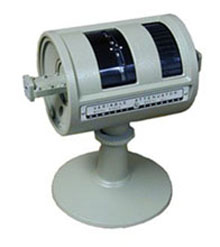
I'm going to guess that the next thing to come along was the 434A Calorimetric Power Meter. The general nature of the instrument was quite unusual. It was hp 's only instrument that had to have its oil level checked before it was turned on - and its oil flow rate checked before applying an unknown input power to its input coax terminal! In fact, the instrument's front panel had windows that revealed an oil reservoir and an oil flow indicator, which windows are respectively labeled "OIL LEVEL" and "OIL FLOW". A simplified diagram depicting the 434A's operation is shown below to the left, while the following quoted "Circuit Description" from the hp 1959 catalog provides a pretty good explanation of its operating principle:
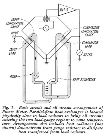 |
"The Model 434A consists of a self-balancing bridge which has identical temperature-sensitive resistor (gauges) in two legs, an indicating meter and two load resistors, one for the unknown input power and one for the comparison power. The input load resistor and (a first) gauge are in close thermal proximity so that heat generated in the input load resistor heats the gauge and unbalances the bridge. The unbalance signal is amplified and applied to the comparison load resistor which is in close thermal proximity to the second gauge so that the heat generated in the comparison load resistor is transferred to that gauge and (substantially) rebalances the bridge."
"The meter measures the power supplied to the comparison load to rebalance the bridge. The characteristics of the gauges are the same and the heat transfer characteristics from each load are the same, so the power dissipated in each load is the same, and the meter may be calibrated directly in input power."
"The power measurement is accurate, because flow rates through the two heads are the same and the oil enters the heads at (virtually) the same temperature. To insure constant temperature and to bring the streams to (substantially) the same temperature, they are passed through a parallel-flow heat exchanger just prior to entering the heads. Identical flow rates are obtained by placing all elements of the oil system in series.".
The "heads" are shown in considerable detail in the view below:
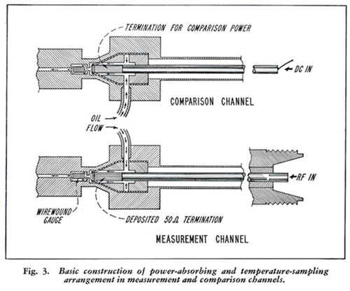 |
Please notice the thin electro-formed shells that terminate the co-ax line id's. They were hp 's first electro-formed parts - 0.005 inch thick Nickel with an etched-out aluminum mandrel.
OK fine - but all of that had been so for many years of development time. The problem was that the 434A still didn't work because of noise, which noise had a magnitude of more than half-scale whenever the 10 mW range was selected! The problem was explained very simply by Bruce Wholey as: "The gauge wire is at least as good a strain gauge as it is as a temperature gauge.". Clearly the problem was that the gauge wire was exposed to turbulent flow, so my task, and ultimately my principle contribution to the by then more-or-less 5-year old project, was to find a way to smooth the fluid flow and shield those wires from it as much as possible - while still maintaining the functionality of the instrument. I also contributed a more efficient radiator that was only about one fifth the size of the previous one - all of this in time for the 434A to be released into production in time to make the 1959 catalog.
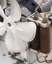 |
That more efficient radiator is shown in the picture at the left. As you can see, it is located next to the instrument's fan motor right behind the fan. It has two short cylindrically shaped finned (e.g., roll formed) tubes. Previously, the radiator had six such tubes each almost twice as long - all set in front of the fan. The secret was that I bored the inside of the tubes such that they had a more-or-less cylindrical bore and then inserted copper rods configured such that the oil had to flow through a radially thin film proximate to the more-or-less cylindrical bore of the tubes. I made an attempt to obtain what would have been my first patent on that idea, but the examiner dug out an old (e.g., from the early 1900's) patent relating to something used on steam engines. So John Chognard ( hp 's first, and still at that time only, in house patent attorney) thought that relating an hp instrument to 50 plus year old railroad steam engine technology was a big joke and didn't argue the case further!
But then a little later came the USAF with its Ballistic Missile Early Warning System ("BMEWS"). Three installations thereof were to be pointed north from remote regions of Canada and England for the purpose of looking for inbound missiles coming over the North Pole. The Air Force had a requirement for measuring the power applied to their RADAR antennas and chose the 434A for that task - except it had to be packaged differently in order to be compatible with their other rack mount instrumentation. Basically (e.g., from my perspective) it was a matter of providing a 5/16 inch thick by 26 inch wide panel and gold alodyned sheet metal - including that odd-ball panel.
However, John Minck swears that they wouldn't accept the instruments without the pump/motor combination conforming to "military specifications". I never knew anything about that problem - because when the instruments were released for production, everything in them including the pump/motor combination, was the regular production stuff (except of course for that alodyned panel and other sheet metal).
Anyway, somewhere along in there came the 938A and 940A Frequency Doubler Sets. They were enabled by really clever conceptual EE design work by Russ Riley who became my "cell" mate for the duration of that project. His contribution was to use a broadband crystal-harmonic generator element for coupling energy from an M-band waveguide 9-to-13.25 GHz source to an 18-to-26.5 GHz output issuing via K-band waveguide (e.g., in the 938A), and from an N-band waveguide 13.25-to-20 GHz source to a 26.5-to-40 GHz output issuing via R-band waveguide (e.g., in the 940A). That miracle was accomplished in a soldered assembly that comprised an elaborate orthogonally disposed soldered assemblage of the respective waveguide sections - except that in each case the larger waveguides were tapered into a ridged waveguide section having the nominal dimensions of either of the smaller waveguides (e.g., made possible because of the extended frequency range of ridged waveguide). We would later make use of such tapered and ridged waveguide in the 11518A, 11519A and 11520A waveguide adapter accessories for the 8551A Spectrum Analyzer, which later work was to be made a whole lot easier as a result of the enhanced electro-forming capability we gained later in the early 1960's higher frequency microwave work.
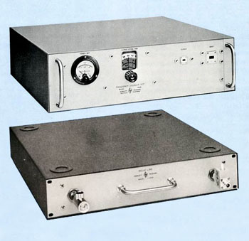 |
In any case, the 938A and 940A Frequency Doubler Sets were functionally configured in a similar manner to the 626A/628A Signal Generators with a directional coupler connected power meter and a 100 db precision rotary vane attenuator. The 100 db precision rotary vane attenuators used in the 626A, 628A, 938A and 940A as well as later in the DY-5636 RF Test Set comprised two serially ganged rotary vane attenuators having a 180 degree bend interconnecting section (e.g., with its own unique resistive film coated mica card) coupling their two center sections, as well as normal input and output end sections.
The two center sections were simultaneously driven by an elongated double worm shaft driving worm gears formed on each with their orientations controlled by a knob and three-turn dial as can be seen in the picture of a 940A shown in the upper picture. As noted above, Larry LaBarre had designed the original M and N band versions of the 100 db attenuators respectively used in the 626A and 628A, so I merely duplicated that basic design for the other instruments. The interesting thing about them however, was that they couldn't be tested because we could only detect power levels through about 50 db of their 100 db ranges!
The strange looking cabinet shown in the picture came about because the 938A/940A's were required to physically support any of the 626A/628A Signal Generators, 686C/867C Sweep Generators or the later 694A/B Sweep Generators (e.g., while they were stacked on top thereof) and thus had to be strong enough to support any of them. One complicating factor was that the 626A/628A Signal Generators were narrower than the 686C/867C Sweep Generators that were packaged in the old 10.5 inch Ralph Lee designed cabinet, or the 694A/B Sweep Generators that were packaged in one of the Clement series of cabinets.
But then a strange thing happened. I was approached by a newly hired ME from the Oscilloscope lab who had the problem of packaging what would become the 1100A Delay Line - which instrument would have to similarly support heavy oscilloscopes. He thought that the packaging concept used in the 938A/940A was just the ticket. So after he explained all of this to me, I gave him prints of the sheet metal parts whereupon he went off happy as a lark.
His boss apparently didn't like the homely appearance of the 938A/940A however, and didn't want anything that resembled them in his lineup of instruments, so the project apparently died - except that it didn't stay dead. Some time later, a more seasoned ME came over and repeated the whole process. This time it stuck, as you can see in the lower picture - where that ME did me one better by providing foot receptacles.
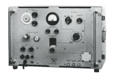 |
The last thing to come along (e.g.,before we moved down to the Lower Floor of the then new Building 3 in 1960) was the news that I was being "loaned" to Dymec to design something that was to be called a DY-5636 RF Test Set, a resulting 1963 catalog picture of which is shown to the left. Other than the above mentioned design of an H-band 100 db precision waveguide attenuator, it was essentially a packaging job wherein I packaged a lot of stuff into a 14 inch high transit case.
Dymec was located down in the old plant complex (up until the big move they had been located in the even older "Redwood Building" at 375 Page Mill Road). This meant that I had to make a few trips down the hill. I wasn't the only person that had to do that of course so hp had a "bus" (e.g., a Chevy sedan) service that ran back and forth between the front entrances at 275 Page Mill Road and the Southwest corner of the then new Building 3.
Now Mr. Packard had his own parking places right outside of private entrances to his offices at each plant whereby you would think that he would just drive between the plants. None-the-less, on one of those trips back up the hill my seat mate in the back seat of the Chevy sedan - was Mr. Packard! And as we pulled up to the new main Building 3 entrance he exclaimed in a manner that betrayed his small town Colorado upbringing, "Sure is fancy isn't it!".
As suggested above, I came to be included in the ME interviewing cadre in 1958. I was informed of this by Ralph Lee who admonished me as follows: "Remember, these kids have only been to school, they don't know anything!" Now while I basically agreed with that sentiment, I certainly wouldn't have been so blunt - but Ralph went right on next saying "I just ask them something simple like 'does Young's Modulus in a piece of steel change when it is hardened?' If they answer no, I figure that they were at least paying attention in school so they must be all right!" I frankly thought that was ridiculous because it seemed to me that what we ought to be primarily interested in how a candidate might go about attacking a difficult design problem (plus of course, we primarily dealt with aluminum, brass and copper).
So I adopted a procedure of presenting either of the 532 or 382 design problems to interviewees in order to see how their thought processes would work when confronted by a tough thought provoking design problem. I have continued to use that method to this day, and up until the 1990's it always worked well. Sometime during the early 1990's however, I was abruptly stopped during such an interview by a candidate who was about to graduate with honors from the University of Michigan. After less than five minutes he stuck his hand out right in my face - and said "You're doing this all wrong! You don't understand, you're asking the wrong questions. They are too difficult for me to answer! They didn't do that at Ford.". And with that, he immediately turned around and marched out the door! Otherwise (and maybe even then), it has never failed to give a good idea about the suitability of a candidate.
Strangely, we found that candidates from the smaller mountain state schools were generally the most likely to be acceptable. In fact, Brigham Young University became our favorite school. I went through four candidates from my own school (e.g., UC Berkeley) before I was able to recommend one (i.e., he had been a Southern California hot-rodder while growing up).
While I escorted the first one into our area (at 1501 Page Mill Road) he had a troubled look on his face. When I asked him what was wrong, he replied "Where are the engineers?" Then the conversation went on something like this: "They're all around you." "No, I mean that all I see are people working at desks, drafting tables and work benches." "What do you think engineers do?" "Oh, I thought that you would have technicians and draftsmen doing that sort of work and the engineers would be in offices." To which I replied "If we could hire technicians and draftsmen to the kind of work we are doing here, we wouldn't need you right!", end of interview.
Mr. Hewlett had an idea that he would like to see a plant in India. So the next thought was that we should interview a mechanical engineering student from India with the idea of bringing him into the plant for a long enough time for him to be "inoculated" with "the hp way" - after which he would return to India and open a new hp plant. That led to my assignment to interview such a student from UC Berkeley (who as it turned out, lived up there at The International House).
The appointment time came and went - and no interviewee. But then suddenly at least an hour and a half later came a phone call from the personnel department saying he's been here all along! It turned out that he had parked in the lot outside Building 1 and walked into the inter-building passageway through the side door - and just stood there for well over an hour! Art Fong was the person who finally asked him if he needed help (e.g., after Art had walked back and forth to Building 3 through that passageway and still saw him standing there). So when I went to get him, I asked "Why didn't you ask someone for help?" He replied, "Well, I had no way of knowing the 'cast' of any of the various people I saw. After all, if it turned out that a person was of a higher cast than myself, I couldn't talk to him - and if such a person were of a lower cast than myself, I wouldn't talk to him!". It is my understanding that that episode cancelled any early plans for establishing a plant in India!
Then there was the graduate student who was being mentored by a professor who was a specialist in "four bar linkages". First he wanted to configure a 532 with a four bar linkage drive instead of a lead screw. Then when I gave up on that, I tried him on the 382 with its multiple turn knob/dial controlling the position of the center section that only went through a quarter turn. Same result, he wouldn't have it any other way than trying to figure out how to fashion a four bar linkage that would do that! End of interview.
And then there was the young man that Bill Girdner wanted to hire for his tool engineering group. My opinion was that he couldn't think in the abstract. That is to say he didn't seem able to grasp concepts and plot any sort of path toward solving a problem. So my recommendation was "do not hire".
But a few weeks later, there he was in the tool engineering department. That was the first (and I think the only time) that a prospective ME that I had turned down was hired. But then again, Bill Girdner came over to see me about six months later and said "We just had to fire that young man. So I looked back through his interview reports to see what we had missed. You were the only one that said 'do not hire'. How did you know?"
In his book entitled The HP Way - How Bill Hewlett and I Built Our Company , Mr. Packard records their long collaboration with Fred Terman of Stanford University relating to getting them (as well as Ed Porter and Barney Oliver) interested in forming the company, and then his meaningful help in actually getting hp off the ground. Over the years both Dave and Bill were significantly involved with and made very significant donations to Stanford. But the specific action that affected me as well as a number of other hp engineers was Packard and Terman's particular collaboration in 1954 that established the Honors Cooperative Program, which program allowed qualified hp (and others from other companies as well) to pursue advanced degrees at Stanford. We hp employees still received our full hp salary while going (part time) to Stanford on company time. In fact, during the period of 1958 through 1962 when I was a participant in the program, hp also paid half of your tuition and book expenses. Plus - since I also had the GI Bill, things pretty much broke even financially for me!
Then a couple of unique things happened as the Spring 1960 Quarter at Stanford was coming to a close. The ME Department at Stanford had decided to institute a Mechanical Design Engineering course during that school year. The entire spring quarter involved the students being given the same fairly difficult mechanical design problem and then being required to execute their design concepts to the point of layout and assembly drawings. The problem the ME Department faced as the end of the quarter approached however, was that none of the department's professors felt qualified to judge and grade the results! So they came to a really creative solution to that new problem. They asked hp and a few other local firms (including IBM, Food Machinery and Ames Lab as I remember) to each select and send an appropriate mechanical design engineer to participate in a two day judging panel that would score each student's design. I was chosen to represent hp on that panel.
There was a wide range of quality in the students' work as you might expect. What you might not expect is that generally speaking (e.g., as the lead instructor told me privately), the most disappointing work had been done by their "best" students (e.g., the ones having the highest grade point averages), while the best work was done by the "worst" students (e.g., the ones having the lowest grade point averages). In point of fact, there was one really outstanding design that had been done by the student having the lowest grade point average of all - a young man named Tony Badger. I was so impressed by his work, that after the judging was over I asked Tony to interview at hp . At first he was doubtful saying "They'll never accept me because if I'm lucky, I'm going to graduate with a D- grade point average.". I assured Tony that I would sponsor him and that I was sure that I could influence the powers to be to recommend hiring him.
Well, as it turned out that promise was pretty hard to keep. But in the end Tony was hired (e.g., by the Microwave Division), and on a Saturday in June we both graduated - Tony with his Bachelor of Science degree, and me with an MS! At that time, we had a pair of projects that were in trouble from a mechanical design perspective - the 8614A and 8616A Signal Generators to be. Fortunately, when Tony came to work he was assigned to those projects, and with a minimal amount of mentoring did a great job designing those instruments.
But this story has to give one pause. Do our universities have the faintest clue about how to go about properly educating our young prospective ME's?
Besides the 8614A and 8616A Signal Generators, there was another, and even more important, project on the horizon, the 8551A Spectrum Analyzer. It was to be one of the most complex (mechanically as well as electronically) and expensive instruments in the company's history at the time of its introduction. Frankly, I couldn't understand why Bruce Wholey hadn't just previously asked me to be responsible for the mechanical design of all three, as he had a year before with the DY-5636 RF Test Set. If that had happened, they would all have gotten into production earlier - probably about a year earlier in the case of the 8551A. But it was the new era of establishing "proper organization, personnel development and reporting". The practical result of that was that each project had its own management and staff of engineers - with no cross fertilization. As far as the 8614A/8616A project went, it seemed early on that the most important thing was introducing the use of PERT Charts for managing a project.
Now as I saw it, PERT Charts had earlier been invented over at Lockheed as part of their effort to convince the government that they really needed their many thousands of "desk jockey" engineers (who would largely find themselves unemployable during the Nixon recession of the early 70's) - when the real design work on the Polaris and Poseidon rockets had been, and was still being done by relatively small groups of real engineers.
The point of creating a PERT Chart was that it highlighted the critical path to project completion. But the main task with the 8614A and 8616A Signal Generators was to efficiently repackage much of the old stuff from the 614A and 616A into 5-1/2 inch high Clement cabinets (along with a novel linearizing cam gear drive and perhaps some new solid state components). So obviously, the critical path involved ME design. I guess that that had something to do with Tony Badger being assigned that task as soon as he came on board. Fortunately, Tony had inborn and/or pre-trained capability and was able to contribute effectively with minimal mentoring as opposed to the training periods described above.
In any case, this change in management philosophy resulted in me being confined to designing even higher frequency waveguide test apparatus (e.g., to 90 GHz). The big problem was that tolerances were getting much tighter (e.g., as tight as +/- 50 millionths of an inch in many cases) so entirely new manufacturing processes were required. We spent a lot of time developing the enhanced electro-forming capability alluded to above. This was mostly an in-house effort although I got some help from the machine and plating shops over at Stanford where they were developing electro-formed sections that were candidates for use in the mile-long linear accelerator (SLAC) (e.g., to be built out behind the Stanford golf course and more-or-less parallel to Sand Hill Road).
We had two major problems: Heavy electro-formed copper tended to form "Popeye Elbows" on male corners - along with voids at anything that resembled a female corner. And of course, the mandrels used for the electro-forming process had to conform to the tighter tolerances. Thus a lot of the work involved new methods of machining. I especially remember that Bud Kincaid in the tool shop and Thurlow Murray in the model shop contributed significantly in that effort. One especially difficult problem was in making the highly accurate and yet highly polished small stainless steel mandrels required for electro-forming the rectangular-to-round end sections for miniature versions of the precision variable attenuators described above (the lower frequency and therefore larger ones were all die cast). But some of the mandrels were relatively simple shapes such as rectangular ones for short sections of straight waveguide, or round ones for the frequency meter cavities - for which relatively simple mandrels could be machined from 1100 series aluminum and then later etched out of a finished electro-formed part. More of that below, but meanwhile please consider the following:
One thing of note that was accomplished fairly early on in this program was the implementation of a superheterodyne receiver that for the first time could actually measure the performance of a 100 db attenuator - that is if we had had one at 90 GHz! Keith Hunton suggested using a motorized phase shifter having its center section turning at 500 revolutions per second (e.g., 30,000 RPM!) in order to generate the frequency shift of 1,000 Hz that was required in order to enable Keith's concept.
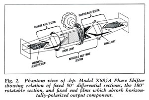 |
Frank Barnett's 885 phase shifter design involved structurally similar (e.g., to the 382 series) rectangular-to-round end sections coupled to a round center section. But instead of the full length resistively coated mica cards, they had dielectric blocks (hereinafter "blocks") of a selected short length positioned in the end sections that were physically set at an angle of 45 degrees to the incoming and outgoing rectangular waveguide - along with a single block of a selected longer length positioned in the rotatable center section as can all be seen in the view to the left. They also had short resistively coated mica cards positioned near the waveguide flanged ends of the end sections in order to absorb any residual horizontally-polarized E-field.
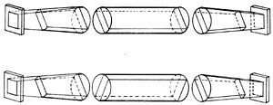 |
Now please take a look at the descriptive schematic drawings shown on the left in order to get an idea of how the frequency shift of 1,000 Hz might be possible. An incoming signal forms two polarized signals that are orthogonal to one another as it passes through the first end section, with the length and characteristics of its block having been chosen such that the signal that is parallel to the block is relatively delayed by a quarter wavelength - so let's call it a quarter-wave section. Then when that combination of signals passes through the center section, those portions of each signal that are parallel to the center section's block are delayed by a half wavelength relative to the other portions of either orthogonal signal - so let's call the center section a half-wave section. Finally, as all of that passes through the other end section (e.g., whose block is identical and set parallel to the block in the first end section), the outgoing signal is put back together in a coherent manner - but with its relative phase shifted by twice the number of degrees that the center section is rotated from a base position (i.e., perhaps as depicted in the view on the top - whereat all three blocks are parallel).
OK, so let's test the above starting with the top drawing. With all of the blocks parallel to one another, the wave front that is parallel to the blocks is actually delayed by a full wavelength but exits in a basically indistinguishable manner from the one that preceded it, whereby we can use that as a base zero phase shifted reference. Then with the half-wave section rotated by 90 degrees as shown in the bottom drawing, all of the wave fronts are delayed by a half wavelength or 180 degrees. You can test this further with other center section rotation values, but trust me - it works! Thus you can see that if one could rotate the center section at 500 revolutions per second, a frequency shift of 1,000 Hz would be generated.
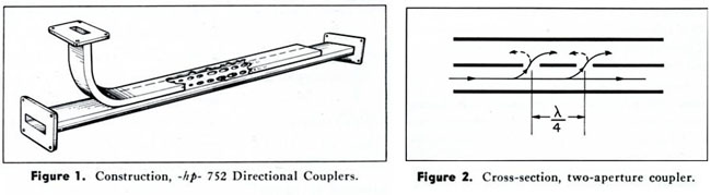 |
In any case, Keith's suggested waveguide circuit comprised two branches of waveguide as implemented by directional couplers such as shown in the above schematic drawings - where the drawing on the right illustrates the method by which such directional couplers are in fact, directional. As you can see, the holes are spaced at nominal quarter wave intervals, whereby wavelets progressing in the forward direction simply pass through but wavelets in the reverse direction are spaced a half wave apart and cancel one another. In Keith's suggested circuit a first one of the two directional couplers was used to create the second branch, while the other was used to eventually bring the two branches back together again. And of course, both branches were powered by a single source so they were frequency wise coherent (e.g., except for the 1,000 Hz frequency shift of course).
The motorized phase shifter was disposed in one branch and an attenuator to be tested in the other. Then with the center section of the phase shifter turning at 500 revolutions per second, the frequency in its branch was either increased or decreased by 1,000 Hz depending upon which direction the center section was turning - whereby a crystal detector placed at the output of the second directional coupler sent a 1,000 Hz signal (e.g., to a receiver) whose amplitude was proportional to the strength of the RF signal coming from the attenuator on test.
Of course, the above shown directional coupler schematic drawings are simplistic in nature. This is because the hole arrays are finite in length and have a beginning and an end. Thus Frank Barnett's directional coupler design included a graduation of hole diameters at each end of the arrays. Why there were two rows of holes instead of one row down the center I don't pretend to know, but assume that Frank was after a selected mix of electric field and current coupling.
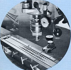 |
In any case, those holes had to be precise in both diameter and location so forming them was definitely a non-trivial task, as you can appreciate by studying the Bridgeport milling machine set up shown to the left.
In any case, we used Bud Kincaid's end section mandrels to electro-form the end sections of both a rotary attenuator to be so tested and the 30,000 RPM phase shifter. Meanwhile I made a deal with a small aircraft motor manufacturer to sell us some 2-pole motor components that had been designed for synchronous operation at 400 Hz (e.g., with a rotational speed of 24,000 RPM) - within which I could position the rotating center section. All of this was somewhat of a challenge but it all went together and worked - except that the thin section high-speed ball bearings obtained from the Split Ball Bearing Company were loud as hell at 30,000 RPM. Needless-to-say, I tended to get a lot of complaints whenever it was running!
As a side note to the phase shifter story - I want to tell you a little more about the development history of the K and R382's. That original prototype that Mr. Packard had picked up and studied so closely back in 1957 was considerably smaller in diameter than the production model. In my youthful enthusiasm I was attempting to design a universal family of X, P, K, and R band 382's just as I was doing with the 532's. So I designed the gear train, housing and other stuff larger in diameter (e.g., with the housing being based upon a permanent mold casting of suitably greater length) such that it could accommodate a proposed X382B. In fact, I built a prototype X382B as well as a prototype X885B Phase Shifter! My idea was to try to get maximum part interchangeability, enhanced tooling, uniform assembly procedures, and hopefully as a result, lower costs. But then along came Ralph Lee who was diametrically opposed to change of any sort. The whole concept went down like a lead balloon without any analysis at all!
"But wait a minute Phillips", those sharper ME's amongst you may be saying. "In order to construct an 885 Phase Shifter in accordance with the concentric design concept you would have had to have an whole number of degrees of center section rotation with each turn of the knob and a vernier dial. (I.e., the production 885's had concentric vernier and direct center section reading dials - with the direct center section reading dial coupled to the vernier dial via a separate gear train.) Therefore, your oddball gear ratio wouldn't have worked!"
And at first blush you would be right because the actual gear ratio of the 382's as they ended up involved 64 diametral pitch gears being used with a radial dimension to the pinion axis of 70/64 or approximately 1.094 inches. The fixed gear had 122 teeth and its meshing pinion gear 18 teeth, while the driven pinion and center section gear had 17 teeth and 123 teeth respectively. Thus the resulting overall ratio was 1/[1 - (122x17/123x18)] or 15.8143:1, whereby one turn of the knob/dial resulted in about 22.76 degrees of center section rotation.
But then one of the guys out in our gear fabrication area said, "I can make you a 122 tooth center section gear on the same 123 tooth pitch diameter and it will run fine". OK, so that's what we did with the resulting gear ratio being 1/[1 - (17/18)] or 18.0000:1 whereby one turn of the knob/dial resulted in precisely 20 degrees of center section rotation.
But the real point that I wanted to make is that I had to wait until 1995 when I traveled to Chemnitz in the former East Germany to really learn about gear cutting! That happened as a byproduct of my visiting the chief engineer of the former Wanderer Automobile factory that the Russians had caused to be converted into an aircraft hydraulic pump manufacturer named Sachsen Hydraulik, and which the West German government (e.g., the next owner) renamed ORSTA Hydraulik - and then made a sweetheart deal to "sell" ORSTA Hydraulik to an American company named Commercial Intertech - of which I was a customer.
Anyway, I finally learned that what is preordained when you use 20 degree gear cutting tooling is that you are generating involute surfaces that emanate from a base circle diameter that is equal to the product of the number of teeth in question times the cosine of 20 degrees, and then divided by the diametral pitch. In my case the correct resulting pressure angles for both of the driven gears should have been equal to the arc cosine of [(139/140) cos 20] or 21.0957 degrees. No matter - with its driven 17 and 122 tooth gears having pressure angles that close to one another, the X885B prototype seemed to work OK.
But the sad thing is that the whole plan had to be aborted. What I should have done was go back to something like the original smaller K and R 382 diameter, and then used 15 and 14 tooth pinions with something like 80 tooth gears - with the pinion axis radius located at 50/64 or about 0.781 inches. Then the ratio would have been 1/[1 - (14/15)] or 15.0000:1, whereby one turn of the knob/dial would have resulted in precisely 24 degrees of center section rotation and a total of 3.75 knob/dial rotations for 90 degrees of center section rotation. In that case the resulting pressure angles would have been the arc cosine of [(95/100) cos 20] or 26.7845 degrees for the 80/15 tooth gear combination, and the arc cosine of [(94/100) cos 20] or 27.9556 degrees for the 14/80 tooth gear combination. The result would have been a total lack of undercutting (e.g., because of the larger pressure angle) and therefore smoother running gears - and it could have been done entirely with the gear cutting tooling then available to us!
There was a measure of redemption sometime later however, when someone totally unknown to me evidently reacted to a marketing request by designing the physically larger M382A using the concentric design concept, elongated housing and all!
But the fact that I had to wait all that time after graduating from two of the highest rated universities in the world and then traveling to the former East Germany before learning how to design a gear train from a person whose tertiary language was English (e.g., after his native German and Russian), and who referred to CAD as "those infernal drawing machines" - only reinforces what I've already said about Mechanical Engineering eduction here in the US!
In any case, all of the above, plus designing two complete lines of miniature waveguide instruments, took a lot of time. But again, our most significant problem was precision machining. Our most appropriate machine tools for this purpose were a Hardinge HLV Lathe and a Tree Milling Machine but neither was really optimum.
But now another side issue: As mentioned above, I had come back from the Army in 1956 with a German wife (e.g., from Munich). At that time I had promised to take her back "home" for a visit just before our first child would be ready to enter the 1st grade. That promise came due in the Spring of 1963. I talked Bruce into letting me take my two weeks vacation plus a week without pay - plus an extra week that I would spend visiting various precision machine tool and inspection equipment manufacturers including one in Paris, three in Switzerland, two in Southern Germany and two in England, as well as our German and English plants and the Instrument Division of Siemens, which facility was located in Munich. He agreed if I would give a talk about all of that to our group of engineers after I came back.
My visit to the Instrument Division of Siemens deserves special mention because it was indicative of the state of German recovery from WWII by 1963. When I was stationed in Munich in 1955 I had gotten permission to take my Ordinance Platoon for a visit to BMW's assembly plant (e.g., now known as the "old plant" and located not very far from BMW's headquarters and the 1972 Olympic site). They were assembling 501's and 502's mostly by hand - even including hand drilling some holes in various brackets and the floor pans.
The Siemens' instrument manufacturing seemed to be somewhat advanced from that but their sheet metal press brakes were a site to behold. That was because they were driven up-and-down by a screw-jack, whereby it took two men to operate the machines! One sat in front of the press brake (e.g., in much the same way as a modern press brake operator does) and fed a sheet metal part between the folding dies. But then for each part to be folded, the second man would then grab hold of one of four levers extending from the screw jack and walk around the machine until the part was folded - and then reverse direction and walk the other way far enough for the folded part to be removed from the dies!
In any case, the most impressive machine tool and inspection equipment manufacturers of the eight that I visited were the measurement tool company Etalon, the Swiss screw machine maker Bechler, and the machine tool manufacturer Schaublin all located in the French section of Switzerland; as well as the milling machine manufacturer Deckel located in Munich. Either of the small horizontal spindle milling machines made by Schaublin or Deckel would have been a gigantic step in the right direction for our model shop but we weren't to purchase a Deckle mill for at least three more years - and we already knew about Etalon and had their micrometers and gages so you might say that that extra week was wasted.
But on the basis of that experience, I suggested to Bruce that I ought to design and build an ultra-precision air bearing spindle and drilling table for hp . He was quite surprised at that and said something like, "You know how to do that?" to which I said "sure" in my most confident tone and proceeded to sketch some proposed air bearing pockets and equivalent circuits describing their operation - in order to demonstrate my supposed prowess in designing air bearings. Amazingly, he agreed to let me undertake such a project!
Fortunately for me, Bud Kincaid was assigned to the project. And largely based on what we went through together to make good on my proposal, we became life-long friends. But after about the third try we had it - just possibly the best performing small air bearing spindle ever built - at least up to that point. Although its parts were made on an existing cylindrical grinder of marginal quality and with other on-hand equipment, that spindle had run-out and cam-action figures of about 1-1/2 millionths of an inch - along with having an extremely low compressed air consumption rate of about 2 Standard cubic feet per hour! Concomitantly, another tool maker named Dick Barth built the drilling platform (i.e., that was cam driven in the vertical direction by perhaps 1/4 inch), which drilling platform fortunately worked on the first try. As you will see below, both of these devices would become important to hp within a very short time - in an entirely unimagined way.
I don't remember the genealogy of the X913A High Power Termination. I may be doing an injustice to one of my colleagues, but I think the concept and lossy coating material came from the outside. In any case, the project was predetermined to result in an air-cooled 500 Watt termination and somehow came to me for implementation.
The material was said to be good for as much as 100KW peak power, so I immediately thought in terms of making the final product capable of being water cooled and thus perhaps being good for something more like 5,000 or even 10,000 Watts continuous. That is the reason for the "screw tread" like configuration of the integrated fins on the broached aluminum casting of the X913A.
But testing the X913A at such a power level, or even at the 500 Watt level, was another matter. We simply didn't have X-band power sources capable of anywhere near those power levels. Then Keith Hunton came to the rescue! He knew someone down the hill in the high power klystron group at Varian. His friend (I can't remember his name - sorry) evidentially owed Keith a favor. One afternoon that got me access to a setup that could deliver such power levels.
In any case, his friend powered right up to the 500 Watt level. No sweat - as I remember it the prototype X913A was quite content while continuously dissipating that amount of power air-cooled. But I had machined the fins in such a manner that they would accept a cylindrical jacket having sealing O-ring grooves and the necessary fittings for utilization as a water load. So I assembled the jacket and talked Keith's friend into hooking up his water supply (i.e., Varian sold 10,000 Watt water loads that he was capable of testing) and powering the setup up to 5,000 Watts. Again, no sweat - we left the setup running at 5,000 Watts more than long enough to know that it could have been advertised as a 5,000 Watt termination.
But confronted with such success, I really wanted to move up toward the 10,000 Watt level that their water loads could handle! But then Keith's friend baulked at the thought of us actually having a competitive product that was a lot shorter (in length) and considerably more versatile in use than their water termination. In the end we backed off and set the published spec at 500 Watts air-cooled and let it go at that in order to keep peace between firms.
The air-bearing project was still going on of course. But just as the guys in the shop were beginning fabrication of the air bearing platform and spindle, the powers that were at the time (Art Fong, Howard Poulter and/or Bruce Wholey?) decided to pull me away from the high frequency waveguide projects and assigned me to the 8551A portion of the 851A/8551A Spectrum Analyzer project!
Fortunately, a person named Karl Johannsmeier had just walked in the door in much the same way that both Norm Bowers and I had previously done. The personnel department immediately referred him to me for an on-the-spot interview. One thing led to another and we hired him as an experienced and capable mechanical design engineer.
Karl had had a most interesting background. He had risen through the ranks at Carl Zeiss Jena (e.g., in East Germany) but had been imprisoned for two years following the 1953 uprising, Later in 1956 (e.g., before the "wall" went up), Karl and his brother conceived a plan that enabled them to travel to East Berlin (e.g., in a manner that could be made into a movie), whereupon Karl then simply crossed over to West Berlin on an elevated public transit train. In any case, Karl's arrival enabled my move to the 8551A Spectrum Analyzer development group because he was able to take over the high frequency waveguide project almost immediately.
As a side note - Karl later became my (senior) partner in a step-and-repeat camera company called Optimetrix and as a result had a significant influence on my career. He became a very successful Silicon Valley personality and investor, particularly as noted below with regard to Acuson. He has chronicled all of this (and a lot more) in his autobiographical book entitled "Wooden Bazooka" (e.g., a name derived from his experience as a conscript in the German Army just prior to General Patton's Third Army's arrival in Jena). Although Karl had written the book in English, it met its real success in Germany after being translated into German by someone named Thomas Bertram and published by Lichtenberg Verlag GmbH of Munich, Germany. It was published with a new and in my opinion preferable title " NEUN LEBEN sind nicht genug, Mein Weg vom Stasi-Haftling sum Erfolgsunternehemer in Silicon Valley" ( Nine Lives are not Enough, My Way from Secret Police Prison to Success in the Silicon Valley). Amazingly, the book became a best seller with Karl making promotional TV appearances and appearing at many book signings.
Karl made a number of gracious references to me in the book - particularly in this case with reference to the beginning period of our relationship at Hewlett-Packard - as follows:
"Der Mann, der mich einstellte, Ed Phillips, setze neue Mass-stabe for mich, Er war der beste Ingenieur, dem ich je begegnet war." (The man who hired me, Ed Phillips, set a new standard for me. He was the best engineer I had ever met.)
The fact of the matter was that the 8551A project was in trouble. By then the 851A/8551A Spectrum Analyzer should have been released into production (e.g., easily in time to make it into the 1964 catalog, but it was simply not ready for that step. I inherited two young ME's who had been hired right out of school a couple of years earlier and directly assigned to the 8551A portion of the 851A/8551A Spectrum Analyzer project. One had done the electronics packaging, and the other the purely mechanical portions (e.g., principally an elaborate gearbox that was used for controlling the tuning and some basic panel functions such as the dial mechanism). Although a more-or-less complete drawing package and a material list existed (e.g., for more manufactured parts (over 200) than I'd ever seen in one box before), neither area was in shape for release. In any case, having me come in like that must have been difficult for those two young men - because most of their work had to be undone and then redone.
Over the next few months I made more layouts and more part drawings during a shorter time period than I'd ever done before. But in spite of that, the main problem hadn't yet been solved! The fact of the matter was that that gearbox had to go! It was a big clumsy thing that didn't work very well and more importantly, it occupied "real estate" that really should have been occupied by various critical electronic items. The problem was that there didn't seem to be any place for mounting any sort of conventional gearbox in any accessible location in the instrument.
But one day I had an epiphany! Why not mount a 1/8th inch thick hard anodized aluminum sub-panel behind the instrument panel and then construct the required gearbox as a collection of meshing gears that had no shafts, but instead would be face bearing stabilized via being directly mounted in holes bored through the sub-panel and held there by retaining rings! I had no idea whether or not it would work, but drew it up anyway and sent the drawings out to the model shop. A week or so later the parts were all finished, and during one afternoon I assembled them on my workbench with the sub-panel held in a bench vise. To my absolute delight it worked!
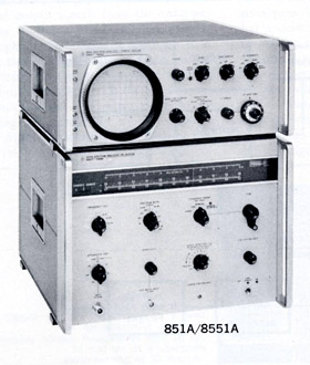 |
But just then it happened that Ralph Lee was walking up the aisle right next to our workbenches and heard me yelling "it works!". He came over and said "What's all this noise about Phillips?" When I told him that I had built a gearbox with no shafts, he grunted and exclaimed "We'll see about that!" - and walked off. Then when I arrived the next morning there was Ralph who had turned the bench vise on its end so that the sub-panel was horizontally disposed. He was holding a paper lunch bag over the gearbox and said, "Went home last night and emptied out the Electrolux!" With that he dumped a collection of Lee household dust, dog hair, and god knows what else on the gears and said "Let's see it work now!" I gulped, righted the bench vise, and grabbed ahold of the control knob - and turned the gears with no trouble at all! That design was a major factor in making the 8551A producible. The finished 851A/8551A Spectrum Analyzer is shown in the picture at the left.
One last note about the 8551A. It featured a multi-decade long phase-locked loop that was analyzed, and in the final analysis perhaps even made possible, by the then recently created Bode Chart technology, which technology had been invented by C.J. Savant, Jr., PhD of the Aircraft Division of the Hughes Tool Company and the University of California at Los Angeles (UCLA). The technology was actually brought into hp by a newly hired EE named Rich Bauhaus who had learned about it as a senior in Electronic Engineering at UC Berkeley.
Meanwhile, Bud Kincaid and I were still "hot-and-heavy" in the air bearing spindle business! And sometime later during 1963 it was finally finished. Bud built a bracket that could be mounted on a Hardinge HLV lathe's bed (or on a Chucker for that matter). Soon Thurlow Murray was using it to diamond turn 50 millionth tolerance electro-form mandrels. This tight tolerance was made possible because we set up a millionth indicator behind the cross slide whereby Thurlow could measure a turned surface with an ultra-precision micrometer (that had its own millionth gage) and then literally control the diameter of the next cut to within 10 millionths of an inch. Perhaps the most interesting thing was that the cut aluminum surfaces were actually diffraction gratings. This as opposed to the relatively crude diamond turned surfaces that one could see on large memory disks of the period. This was because in those cases, their diamonds were actually set up as burnishing tools.
But soon thereafter, the whole ultra-precision waveguide project was cancelled because of the invention of the laser! It was decided that future advances in communication would be handled optically with information bearing light energy traveling through fiber optic bundles. Of course, that didn't actually happen for the better part of 30 years, but no matter - all of the stuff that had been constructed (e.g., except of course the air bearing equipment) along with all of the drawings were put in a box and stored away in some warehouse - never to be seen again as far as I know.
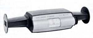 |
One thing that did survive however, was the general design concept for a precision rotary vane attenuator in the form of the soon thereafter created S382A Precision Rotary Attenuator shown to the left (e.g., done by others - not me). Its dial is directly driven from a horizontal knob and shaft - with an anti-backlash loaded spur gear train then being used to couple the shaft to the center section.
Sometime later in the winter of 1963/1964, Paul Stoft looked me up and made an offer for me to come to his fledgling group that either was, or was about to be called hp Laboratories. The offer included becoming his ME section manager. And since the offer included a $200 per month raise, it wasn't hard for me to accept!
In any case, the 8551A project was just about done. All that was left to do was finish the gearbox portion of the project - including repositioning the other components and completing the paperwork (i.e., such as material lists and Kardex cards etc.). A young technician named Dave Veteran came into the lab just in time to do that (e.g., after the two young ME's transferred to Colorado Springs) and he quickly moved the project to completion - and as they say, the rest is history. The 851A/8551A Spectrum analyzer quickly became ($-wise) the largest selling hp instrument - and it rejuvenated the Microwave Division under a new division manager named John Young.
Being in Paul's group was very nice, but frankly without much challenge. The only projects that were in any way mechanical in nature were the infamous "bandsaw recorder" (a term that I believe was later coined by John Young after it was "foisted" on the Microwave Division) and an early dot matrix printer concept that was trying to find a home. The idea behind the dot matrix printer concept was to take paper having thin aluminum foil bonded to it and then coat the aluminum with a white coating that turned a darker color when electrical current flowed through it (e.g., to the aluminum and an exposed edge that was grounded). We got the paper locally (e.g., somewhere up the peninsula near SFO I think) from the same outfit that produced Kaiser Quilted Foil boxes for Kaiser. In any case, our circuitry selectively applied current to the coating in columnar 5 X 7 matrix formats from five outstretched fingers per column that extended from a PC board.
Livermore Labs (e.g., the facility near Livermore, CA that was run for the government by UC Berkeley) had a nominally competitive page width printer that reportedly ran at a speed of 500 lines per second. Well hp being hp , we had to do them one step better so we determined to make one that ran at the rate of 1,000 lines per second.
We decided to first build a 1,000 lines per second printer that would only print 20 columns. We used paper/aluminum foil tape about 2-1/2 inches wide which allowed us to borrow from hp 's tape deck technology (e.g., with servo motor controlled reels and tape loops for paper handling etc.). And we did it - we succeeded in building a printer that indeed printed at 1,000 lines per second! But it consumed paper at the rate of about 14 feet per second - so even our 9 inch or whatever diameter spools of paper hardly lasted long enough to demonstrate the printer. This led to wiser heads entering the scene and someone higher up the food chain (perhaps John Cage) got permission to look at the machine over at Livermore to see what in the world they were actually doing with it.
He found that the printer was positioned more-or-less in the center of a large heavy duty frame that had provision for mounting two 4-foot diameter rolls of paper one above the other on an "input" end where a fork-lift truck could load one roll while the other was being consumed. The operation consisted of continually running the printer (e.g., at the 500 lines per second printing speed) to record either 1's or 0's that were somehow representative of a process that was being monitored. The printed paper was immediately fan-folded as it came out of the printer. As the printed and fan-folded paper moved on down a track on the large frame, two technicians were responsible for continually opening the fan-folds and looking for any 1's. Whenever such an event happened they would cut out that section of fan-folded paper from the train of fan-folded paper. Then as such "meaningful" printed pages built up, they would bind them into books that presumably someone was going to analyze. The rest of the fan-folded paper then simply moved on into an on-line incinerator where it was burned up! It was soon thereafter decided to cancel the printer project
The tool shop was run by a big fellow named Swede Wild - almost Mr. Packard's size. They were friends and I believe they had been known to take fly-fishing trips together. In any case, one day Mr. Packard was down in the tool shop talking to Swede while a nearby air-motor wielding toolmaker named Lyle Muth was polishing cavities in a plastic mold. Now regardless of the fact that Mr. Packard had degrees in electrical engineering from Stanford, I claim that he was really a mechanical design engineer at heart - so naturally he wanted to go take a look at the plastic mold polishing process. When the two of them came over to Lyle's bench, Mr. Packard couldn't resist sticking a finger into one of the cavities to feel its polished surface.
Well! Lyle drew himself up the his full 5 foot 6 inch or so height, and said "Swede, can't you keep the big guy's fingers out of the molds!" Then Swede simply said "Lyle Muth, meet David Packard." That was it - except that a week or so later Mr. Packard was walking down the aisle that separated the tool shop from the model shop, and as he passed Lyle's bench (e.g., with Lyle at work polishing another plastic mold), Dave stuck both hands in his pants' pockets and said "See Lyle!".
As far as I knew, HP Associates got serious about actually building their first LED's during 1963. This was before the availability of any sort of mask/wafer aligners (i.e., such as a Kasper or Cobuilt) so they thought in terms of doing mechanical mask aligning. Since each level of masking could use round holes, their idea was to drill a large pattern of perhaps as many as 64 holes square (4,096 holes total) of descending sizes in three masks made from 0.001 inch thick stainless steel shim stock along with additional alignment holes so that they could mount each in succession for the three required levels of masking (e.g., via doing so in a jig). As I remember it, the three drill sizes were 0.007 inch, 0.004 inch and 0.0016 inch (e.g., 0.04 mm). They tried to do this by indexing a Levin jeweler's drill press and then manually cycling its drilling platform. They apparently had little trouble with the 0.007 inch diameter holes, and they could occasionally drill a 0.004 inch diameter hole - but they never succeeded in drilling a single 0.04 mm diameter hole! As I later analyzed it, the principle problem was cam action in the drill press's spindle. During a dwell phase the surface of the stainless steel would work harden, and then when the drill next tried to advance it couldn't break through the work hardened surface and instead snapped off.
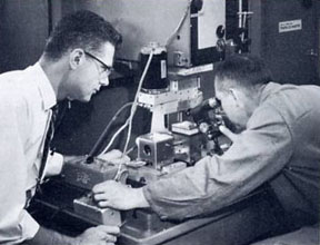 |
I don't remember who from or how I inherited that project, but by then I had acquired the in-house appellation of "Mr. Air Bearing" so that may have had something to do with it. In any case, Bud Kincaid and Dick Barth (e.g., along with the help of an EE named Bob Kirkpatrick) set up the equipment under our then one and only Pratt & Whitney tape controlled drill press as shown to the left. The drilling platform was affixed to its numerically controlled table and the air bearing spindle to the underside of the machine's spindle mounting structure. The setup was such that when the air bearing drilling platform had completed a drilling cycle (e.g., by moving up and down), a microswitch closure wired in parallel with the tape advance button caused the tape to cycle, with the Pratt & Whitney drill press's table then advancing to the next position. Then when the machine's ready light came on, the drilling platform would cycle. (I know the picture was taken after I had gone to Paul Stoft's group because I remember from whom I borrowed the tie - but I don't remember who the machine operator in the picture is - its neither Bud nor Dick.)
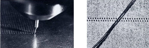 |
You could really see what was going on because we set up a tool maker's microscope and strobe light, whereby you could actually see the very small spade type drills smoothly forming curling chips of stainless steel (remember, the spindle only had about a 1-1/2 micro-inches of cam action). The picture on the left above is of one corner of a 0.004 inch diameter hole pattern (e.g., of 4,096 holes) as viewed through the microscope, while the one on the right is of a demonstration pattern of 0.04 mm diameter holes on 0.004 inch centers with one on my (then dark) hairs draped across it for contrast.
Not only could we drill the 0.04 mm diameter holes, we could drill complete and even multiple masks thereof before replacing the drills, and then only because they wore down and were making holes that were too small! You can read about all of this in an article (from which the pictures were taken) that appeared in the March 1964 hp Journal. That article was written with extraordinary care and attention by the hp Journal's editor Frank Burkhard. The only problem with it however, was that various potential customers read that article and for months afterward I kept getting requests from people or companies that were interested in buying the air bearing equipment!
It was about then that Bud and I along with Harold Pinter and Dick Rasmussen decided to start an Air Bearing side venture. Dick bought a small job shop named Herco down in San Jose and Harold (somewhat of an adventuresome gambler type) left hp to run it. Soon thereafter, Dick also left to join Wiltron (a then young company trying to compete with hp 's microwave sweep generators). The combination of Herco and Bud Kincaid made a number of air bearing platforms, a few of which we sold to Glen Herriman for use in hp 's standards labs.
I had some thoughts about using air bearings in conjunction with Larry Hubby's quartz crystal pressure transducer and possibly also with other of his projects, so a little later I approached Mr. Packard about bringing our fledgling company back inside. He seemed to think that that made sense and said to approach him later after he had time to think about it some more. But then I made a stupid mistake. After a few weeks I found that Mr. Packard was out of town so I approached Mr. Hewlett, who immediately responded in his quick manner - "We don't want to do that!". Then later after Mr. Packard had returned, he told me that he was sorry but he "couldn't go against Bill" and so eventually the outside air bearing business died a quiet death.
The following paragraph is quoted from Mr. Packard's book, The HP Way :
"I remember the problems one particular acquisition caused us back in the mid-1960's. We acquired a company named Autodynamics, headquartered in Sacramento, California. It specialized in using ultrasonic energy to detect flaws in metals. This was before the use of ultrasound in medical applications."
I believe that Autodynamics was one of John Cage's acquisitions - but no matter. It wasn't actually located in Sacramento. Rather, it was located on Bolsa Avenue down in Garden Grove, California in a very small WWII prisoner-of-war facility (I'm not kidding) that had housed German prisoners of war whose daily occupation had been working on roads in Garden Grove and nearby Anaheim (better than getting shot at I'm sure). The Sacramento connection actually relates to Autodynamics' only real customer, Aerojet-General Corporation. Aerojet-General was a rocket maker having a large property in the Rancho Cordova area east of Sacramento (e.g., where placer mining for gold had previously taken place). I know all of this because I inherited Autodynamics during the very week of the Watts riots in the Watts section of Los Angeles.
I remember watching that happening in a hotel room in LA on the evening news and then driving down to Garden Grove the next morning to take over the new acquisition. The WWII prisoner-of-war facility was a very strange place to try to operate a company, so naturally I asked about it and immediately heard the prisoner-of-war story. Other than that, they had four employees - the previous owner, an electronics engineer, a technician and a secretary. The product that they had sold to Aerojet-General was a large (e.g., to be water filled) square fiberglass tank approximately 9 X 9 feet in area by about 4 feet deep with a rotating inspection table located in its bottom. The problem was that - as Mr. Packard put it ever so gently in his book - nothing worked! So rather than the eight months he talks about in the book, we basically folded Autodynamics up as soon as possible and shipped the tank and electronics up to 1501 Page Mill Road.
The only employee we kept was the technician, Frank Brown, for whom (so help me god) we rented a U-Haul trailer so he could move his wife and himself up to the Palo Alto Area. As a side note, the shipping company (e.g., for the company's equipment and files) was located in Watts - and I remember driving through the streets there in convoys behind a Sheriff's car in order to deliver drawings and office files, and later to make arrangements for shipping the tank.
In any case, I can well imagine that the main reason the whole thing stuck in Mr. Packard's craw was that the tank was so big that we couldn't get it inside the building, whereby every time he was on the North side of the building complex at 1501 Page Mill Road he couldn't help but see it! When Mr. Packard says that "We rescued that contract with money and some technical expertise from hp Labs.", he primarily meant Don Miller who redid the electronics.
We actually had no intention of being in the inspection tank contracting business of course. I'm pretty sure that John Cage had been thinking of a possible medical ultrasound application for the Autodynamics ultrasonic transducers (e.g., for Sanborn). That was the reason that I wanted Frank Brown, because he was the one that had done that work for Autodynamics.
In any case, we next began a rather intense period of ultrasonic transducer development in a small room in the back of the lower floor of Building 3. That was because as we got into the transducer technology it quickly became apparent that several improvements could be made. We obtained better piezoelectric materials (PZT's) from Channel Industries in Goleta, California. We developed better absorptive load materials and shapes (co-invented by Donn Lobdell). We designed more sophisticated housings. And we made concave focusing (e.g., lapped) transducers that had vacuum-deposited electrically-conductive coatings. Thus we acquired a lapping machine and vacuum deposition equipment. At that point we really did need more help and so another technician named Bob Starr was assigned to our little group.
We used that new technology to build A-scan (e.g., one dimensional) transducers. Concomitantly, one of Paul Stoft's EE's (sorry I don't remember who) designed electronics that were used with a memory oscilloscope and a scope camera to power and then record the ultrasonically generated data. But our real goal was to devise enhanced apparatus that would be able to provide B-scan pictures (e.g., two dimensional pictures similar to those obtained today with modern medical ultrasound). One of the EE's (I'm sorry but again, I can't remember whom it was) did mention the possibility of doing it with a phased array of small transducers and then utilizing a computer to reconstruct two dimensional images. But we really didn't have the expertise to do so - even if suitable computers for the job had been available in the mid 1960's. That would have to wait for a future hp engineer named Sam Maslak - to leave the company and form Acuson (and of course to then do the necessary development work).
Our solution was to build an "inside-out SONAR system" having an A-scan transducer slowly moving over a patient along something like a 1-foot radius arc, with the transducer generally pointing inwards but swinging back-and-forth through perhaps +/- 30 degrees. I designed a monstrosity of a machine that had a water storage tank, pumping apparatus and plumbing, as well as an arc-shaped track (for the transducer to move along) - with the mechanism separated from a patient laying on a gurney thereunder by a tunnel shaped rubber bladder!
That meant that while a scan was being performed, the patient would be "trapped" for perhaps 10 minutes or so under about a 1-foot head of water bearing down on his or her torso. Naturally I was somewhat concerned about that, so one evening I brought my then seven year old son Mike into the lab and tried it out on him! After the water was pumped over onto Mike I asked him how he was doing - to which he replied "its OK dad!", so I figured we were going to be all right.
But what I hadn't figured on was the fact that doctors aren't engineers! We had made an arrangement for a very small clinical study of the new technique to be done at the Stanford Medical Center. But every once in a while the medical staff there would get the water transferred onto a patient and then manage to have the pump loose its prime - with the result that the patient would be trapped under all of that water until one of us could drive over to the Stanford Medical Center to re-prime the pump (the Stanford Medical Center unfortunately being on the other side of Stanford University and quite a distance from 1501 Page Mill Road!).
But by that time (1966) I wanted more of a technical challenge. I was most interested in designing ultra-precision apparatus, and as it happened, I was made an attractive offer by Tydeman Machine works to design and build ultra-precision machine tools and ultra-precision machining and grinding spindles. I took that offer and tendered my resignation to Paul Stoft. Then sometime within the next two weeks there was a nice luncheon and parting gift for me.
As a side note, by that time I had been at hp for slightly over ten years so I mentioned to Paul that I would appreciate receiving an hp 10-year pin. This was a somewhat unusual request because firstly, no one realized that I would want one, and secondly, they were typically given out at the end of the year. In any case, the result was a simple one-on-one meeting between Mr. Hewlett and myself (e.g., in his office) where he presented me with my hp 10-year pin - which I still have.
But the person who went out of his way to try to understand why I was leaving was Larry Hubby! Larry made a point of seeking me out and asking about that in just so many words. He really seemed to be upset with the news that I was leaving - finally saying, "Well perhaps someday we will know the real reason you are leaving!". He obviously had something in mind but didn't go any further. It's pure conjecture at this point all these years later, but perhaps if he had told me about the laser interferometer project and had taken steps to have me join it, I wouldn't have left - but then there was that little matter of having been turned away by Mr. Hewlett which hadn't only effected me, but others as well.
I had more-or-less continuous contact with hp people for the rest of my time in the Silicon Valley (e.g., through 1984). My friend Dave Cochran helped me with circuitry for driving high frequency SCR Inverters during my "oil patch days". I had a thought that making an oil well into "an inside out sonic cleaner" might somehow be useful in the then new field of secondary oil recovery. I designed and built resonant high energy sonic devices that caused pressure waves to resonantly travel around inside of a well casing and broadcast sonic energy out into the surrounding formation - hence a need for the high frequency SCR Inverters for driving the devices. Dave even made a couple of trips down to the Bakersfield area to help.
Unfortunately, the Nixon recession soon played havoc with our funding source, so at the suggestion of one of my board members I applied my newly acquired knowledge of SCR's to designing an uninterruptible power supply (hereinafter "UPS") for the purpose of supporting the large computers of the day (i.e., such as IBM 360's and 370's). Meanwhile I supported myself by working as a consultant for Karl Johannsmeier, by then VP Engineering at Kasper Instruments (e.g., that company having been funded by John Young and others at hp). I designed some portions of the Kasper 2001 during 1970 - while I was busy finding a new partner named Lee Cooper (no connection with hp ) and seeking funding for what turned out to be Programmed Power, Inc.
Lee had been with Fairchild and knew Gordon Moore and Bob Noyce who had just been able to fund their fledgling company (e.g., named Intel Corporation!) with something approaching the then unheard of sum of five million dollars. We visited Bob Noyce at their initial 20,000 square foot or so building on East Middlefield Road in Mountain View - where we found Bob sitting there dreaming of building an electric car - but unfortunately of no help to us in finding funding.
Then toward the Fall of 1970, some hp folks came to our rescue in the form of company named Royco Instruments that was located in Menlo Park and had been funded by Hewlett, Packard and various hp vice presidents. Barney Oliver took an interest suggesting that I incorporate an electric motor in the UPS machines to smooth out the three-phase voltage waveforms. But that was a problem because the equipment was supposed to be solid state - and was to be located right next to a CPU in the large computer rooms of the day. But no matter, we got "face time" with the company president, Jim Weersing. Jim had been the center and captain of the Stanford basketball team during the 1957-1958 season while Mr. Packard had of course occupied a similar position at Stanford during the 1933-1934 season. Do you sense a possible mentor relationship there?
Anyway, one afternoon we had an hour's face time with Mr. Weersing. He had told his secretary to hold all calls, but clearly he wasn't buying my "song-and-dance" when suddenly the phone rang! At first he seemed to be annoyed at that - but next, if you can imagine a 6 foot 8 inch or so man coming to attention while sitting at his desk and holding a telephone then you have have an idea of what we saw! Only Jim and his secretary, knew who was on the other end of the line of course - but this is more-or-less what we heard, "Hello sir. Yes sir, they're here sir. Yes sir, I will sir. Goodbye sir.", after which he hung the phone up and said, "We'll do the deal."!
I never saw either Mr. Hewlett or Mr. Packard at Royco, but I do remember seeing both Barney Oliver and Ed Porter at Royco board meetings as well as Mr. Packard's old machinist buddy Charlie Litton (i.e., that he talks about so much in his book The HP Way ). Charlie was very friendly (as were Barney and Ed of course) - but he very carefully referred to Litton Industries as "The company that bears my name!".
Every six months or so during the years that I was working in the Royco building on the Programmed Power Project, Karl Johannsmeier would call and ask, "Edward, are you broke yet? Do you want to come to work for me at Kasper?", to which I finally replied one day during the Summer of 1975, "No Karl, I'm not broke - but Franklin Electric just bought us out and I'm available!".
With that I joined him at Kasper - just as John Young had concluded a buy-out deal with Cutler-Hammer for them to wholly acquire Kasper Instruments. No matter, we got along well with the Cutler-Hammer folks who pretty much left us alone to do our thing. Well, about a year later Karl and I broke away from Kasper to form Optimetrix - with financial backing from Cutler-Hammer!
It seems that virtually all new technology-based startups are messy. Programmed Power certainly was, and Optimetrix was no exception. I won't bother you with the details but early on we managed to lose at least a year going down a couple of wrong paths, so in reality we didn't have much more than about two years net time for a development team of only five guys to develop one of the most complex machines in the world. I can't tell you how many assemblies I designed. But one draftsman and I turned out more than 3,000 finished part designs during those two years - even as a then very young Larry Wise (no hp connection except that his father Bill was briefly employed as an EE by hp during the 1950's down in the old lab) developed enough circuitry to fill some 72 printed circuit boards, and former hp Laboratory EE Jerry Alonzo wrote (and remembered which was the scary part) over 500,000 lines of hexadecimal machine code utilized for controlling that 2,000 pound optical machine that had some 27 functionally operating servo systems! Larry Hubby contributed a proposed aspheric fused silica lens design (e.g., for use in the machine's Hg arc light source). And even our old friend Dave Cochran helped out with a novel alignment target and alignment scheme. Then some time later, Bud Kincaid left hp and came to join us.
All of this led to some 21 of my 105 thus far issued US Patents - with most of those 21 patents being written by my good friend Ron Griffin (e.g., on the hp friendly moonlighting basis mentioned above of course). Almost all of that work took place in Ron's home up in the "Pink Horse Ranch" area of Los Altos Hills (e.g., just off of Moody Road). But from time-to-time I would briefly visit Ron up at hp . Interestingly, while driving away from one of those meetings I happened to see Jim Weersing drive hurriedly through the parking lot and right into Mr. Packard's fenced off private parking area just outside of his office! Now that was a mentoring relationship for sure!
Incidentally, you would think that our project would have gotten some interest and maybe even some support from the Federal government. But the only "help" we got from Jimmy Carter's administration was a monthly visit from the CIA to make sure that there had been no contact traceable to an Eastern Block country!
That was in sharp contrast to Japan, Inc. where the Japanese government had directed both Nikon and Cannon to develop step-and-repeat cameras and then backed their efforts with substantial grants and zero-interest loans - or to the Netherlands where Philips developed a step-and-repeat camera with Carl Zeiss Oberkochen's help, and then split off the resulting product to form KLM Lithography.
The Optimetrix story of course was quite different. We started out with minimal financing - and it got worse! Along the way, Cutler-Hammer was acquired by Eaton Corporation - whose Chairman, De Windt, didn't like the terms of our original deal and grew to strongly dislike Karl Johannsmeier. In fact, he became determined to force us into bankruptcy! Karl managed to overcome that problem however, by selling 10 machines (that weren't even completely designed at that time) to National Semiconductor - and collect 30% cash with the order, with which we managed to complete the development of the Optimetrix step-and-repeat camera!
Finally, Eaton bought us out. What would a truck-axle manufacturer know about step-and-repeat cameras you might ask? Answer - not much! None-the-less, the original Optimetrix stepper was chosen by a few - most notably Motorola in Austin, Texas, Hyundai in Korea, and OKI in Japan. In fact, OKI bought some 40 machines, and with them became the most efficient manufacturer of memory chips in the world (e.g., during the mid 1980's). In fact, they were the only company found innocent during the US government's legal action against four Japanese memory chip manufacturers (e.g., because OKI had been so efficient that they had consistently made a profit!).
None-the-less, the technology moved on and Eaton-Optimetrix fell by the wayside. Since the mid 1980's there have been no creditable US manufacturers of step-and-repeat cameras - to the detriment of our balance of payment problems of god knows how many tens of billions of dollars.
But just to complete the story - in 1986 a new partner named Bill Weinstock and I, attempted to start a new step-and-repeat camera company - and we found real interest from various agencies of the British government. We were entertained by the Welsh and Scottish Development Agencies as well as the Department of Trade and Industry (the "DTI").
Our problem was that the DTI had just been put through a financial wringer by John DeLorean and his DeLorean Motor Company that the DTI had financially supported in its failed attempt to bring auto manufacturing to Northern Ireland. That costly episode had resulted in an absolute edict against any DTI funding of other new ventures - unfortunately such as ours. They did however, eventually offer to give us a property that had recently been vacated by Texas Instruments in Plymouth, England and was worth some 19 million dollars - that is if we could raise the necessary funding to start actual product development from "The City" (e.g., the financial hub of the UK located in the center of London). We received support from Rutherford Labs (the UK's answer to Livermore labs) and Cranfield University (of "The Dambusters" fame) in that effort. Even Gerhard Ittner of Carl Zeiss Oberkochen (then the most respected opto-mechanical engineer in the world) wanted to join us. Gerhard few to London on his own "Deutsche Mark" to attend meetings and do what ever he could to assist us in getting financial support. Further, Wild Heerbrugg AG of Heerbrugg, Switzerland sent two optical designer/engineers to evaluate my optical concept and support us. But in the end it was no use, the British financial community wasn't swayed and the project simply died.
OK, so now back to something relative to Larry Hubby's question. What difference could I have made in the laser interferometer program? Please consider the following:
One of the toughest problems in applying laser interferometry is on the customer's side. Suppose that a customer wants to accurately control an X-Y stage using laser interferometer position feedback. His toughest problem is making sure that the two required orthogonally positioned stage reference position mirrors are really orthogonal to one another. Because of this, such mirrors are often formed as two sides of a single block of reflective material. But even then, the orthogonality of the two mirrors is ultimately dependent upon some orthogonal angular measurement standard, the true orthogonality of which may well be in question.
Angle standards are a tough proposition. By way of example, I remember Glen Herriman's story about trying to get a 30 degree "jo block" certified by the National Bureau of Standards ("NBS"). After he bought it from Starrett he immediately sent it off to the NBS to be checked and certified. It took an extraordinarily long time for his 30 degree "jo block" to be returned with the certification - but when it did come back it was certified to be out of tolerance - by a factor of three times! Glen wanted to know how the NBS had determined that, so he asked - and was told:
"We didn't have a 30 degree standard so we bought another 30 degree "jo block" from Starrett that is identical to yours and found it to be different from yours by our stated amount. Since by definition ours is correct, then yours is out of tolerance by the stated factor of three times!"
Needless to say this was not very reassuring, so please consider the following idea as explained in my US Patent No. 4,311,390 dated January 19,1982 assigned to Optimetrix:
The drawing below is from that patent. It depicts the Optimetrx Step-and-Repeat Camera with a one-time experimental laser interferometer stage position measuring apparatus we attempted to set up thereon (e.g., with the machine shown in schematic form). The lower stage 16 is supported on air bearings (not shown) and moves physically in a nominal X direction. The upper stage 20 is also supported on air bearings and moves in the nominal X direction with the lower stage 16, and also moves in a nominal Y direction with respect to the lower stage 16. A mirror block 34 is mounted on top of the upper stage 20. It has first and second flat mirror surfaces 30 and 32 that are oriented symmetrically about an actual Y-axis of motion, where the mirror surfaces 30 and 32 have an included angle therebetween of 2θ. The upper stage supports a wafer chuck 22 that has rotational capability upon which a wafer 12 can be mounted and aligned.
The upper stage moves along precisely orthogonal X and Y axes as specified by X and Y digital end point data signals as effected by X and Y position control circuits in accordance with the equations: ΔX = ( ΔL1 - ΔL2 ) Cos θ and ΔY = ( ΔL1 + ΔL2 ) Sin θ - where ΔL1 and ΔL2 are the displacements of the first and second flat mirror surfaces 30 and 32 along respective measurement paths of first and second interferometers 66 and 66'. In this case the measurements of length are shown relative to first and second stationary mirrors positioned on a reduction lens 26 (e.g., where the reduction lens 26 projects an image of a reticle 14 upon portion 38 of the wafer 12) - and further where a customized value for θ (e.g., unique to that particular machine) is determined in accordance with the following calibration procedure:
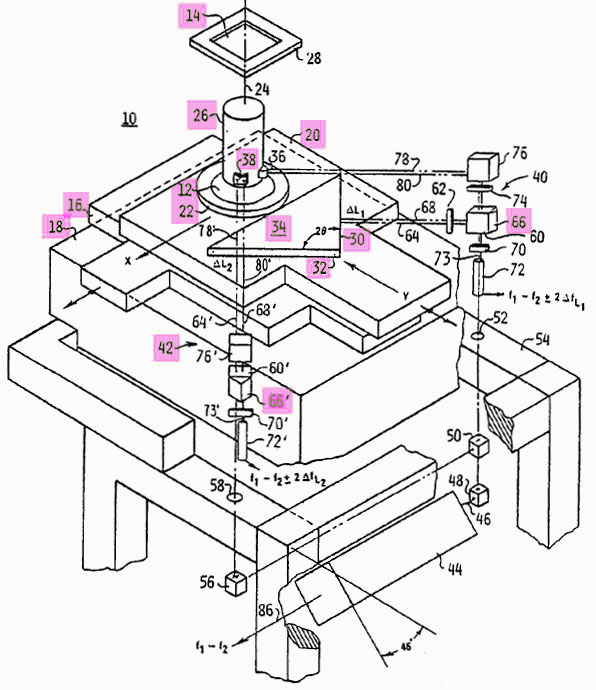 |
After the laser interferometer becomes operational, a mirror or corner cube is set upon the wafer chuck 22 and an external single axis interferometer is used to measure a displacement along either of preliminary X or Y axes (e.g. with the stages having been moved in accordance with an assumed value of θ equal to 45 degrees). In general, there will be an error in displacement because of a probable non-orthogonality between the first and second flat mirror surfaces 30 and 32. Thus, the corresponding equation (e.g. for ΔX or ΔY) is then solved for the actual value of θ . Then via utilizing the actual value of θ in the equations , the resulting displacements along the X and Y axes are correct and they are precisely orthogonal because (by definition) Cos θ is orthogonal to Sin θ .
Of course, this illustration is highly simplistic because it depends upon each set of air bearing alignment guide blocks being set up precisely parallel to one another (e.g., so that the stages don't suffer a yaw rotation), as well as the supporting surface 18 on the step-and-repeat camera's granite base 42 being absolutely flat (e.g., so there is no Abbe offset error). In reality one should utilize a five axis interferometer and position the mirror block 34 such that it precisely mimics the motion of the wafer chuck 22 (note however, that the wafer chuck would still have to have an angular adjustment capability therewithin in order to align each wafer with respect to the resulting X and Y axes of motion).
We did attempt to implement the system shown above, but found it to be extremely hard to align. The biggest problem was that the so-called "Universal Mounts" weren't really universal! That is to say that they were limited in that they only had two rotational degrees of adjustment freedom - either pitch and yaw, or roll and yaw depending upon which way one attempted to use them (e.g., when of course they needed all three) coupled with the yaw adjustment tending to move when the clamping screws were tightened. I'd like to think that I could have made some contributions.
In any case, instead of putting up with all of that, we utilized a large fused silica plate that was mounted directly under the wafer chuck and viewed from below (e.g., through by a vertical hole in the granite base 42) by a microscope objective underneath. The fused silica plate had a two-dimensional array of 10 X 10 micron sized square chrome dots on 20 micron centers. The microscope objective projected an observed section thereof on a sub-stage mounted two-dimensional detection plate (e.g., as well as detectors located therebehind). Then when a new stage position was commanded, the stage was moved in accordance with rows and/or columns of dots being accordingly counted by a two-dimensional up-down counter concomitantly with the sub-stage suitably re-positioning the two-dimensional quadrature sensitive detection plate.
Early on at Optimetrix, we had a problem with final position overshoot of the commanded X and Y addresses. But at the same time, Karl Johannsmeier was giving modest financial support to Sam Maslak and his partner Robert Younge (who had also left hp Laboratories to join him) in their Acuson venture. So it was natural for Karl to hire them as an electronic engineering team commissioned to solve our stage overshoot problem. The problem was in fact solved by Sam as follows: As either stage got to within a predetermined distance from its final address, its velocity was (e.g., in "open-loop" fashion) commanded to descend linearly in proportion to "the distance to go". Thus both stages would theoretically be traveling at zero speed when their distances to go were zero, although "closed-loop" control was initiated when the stage was close to its final position (e.g., literally controlled to within a few millionths of an inch).
Note: If by now you have figured out that designing and building a step-and-repeat camera is a non-trivial task, you are right! These machines are probably the most accurate and sophisticated pieces of equipment in the world (e.g., with a current selling price in the order of $10,000,000 - the lenses alone now having a cost of about $500,000!). Unfortunately as indicated above, there are no credible US manufacturers of this type of equipment left.
David Packard was dynamic person who had no trepidation about bringing new ideas into hp. Starting in the 1950's and then on into the 1960's, hp sought out a number of externally sourced technology and business opportunities. For instance, when I arrived in 1956 there were a couple of Swedish engineers working on what became the 340 series of Noise Figure Meters and Noise Sources - which basic technology I believe had been purchased from a Swedish company.
Then as Mr. Packard says in his book, hp acquired the F.L. Moseley Company in 1958. He also says that Sanborn was the largest firm that hp acquired during the 1960's. This confuses me somewhat because of the above reference to Carl Clement's group working on the first EKG machine that wasn't in a roll-around wooden box during 1957 when we were in the back of the old lab at 275 Page Mill Road - as well as the Wikipedia sourced information presented below.
In 1961 hp did execute a deal with Jack Melchor to form hp Associates. Then in rapid fashion came the Boonton and Harrison Laboratories acquisitions. But of course, there also were the less successful "bandsaw" recorder (also from Sweden I think) and Autodynamics acquisitions.
But to many of us, the strangest acquisition was that of a very small local company that became known as hp 's Delcon Division. They had a product called an "ultrasonic translator", which device comprised an ultrasonic home TV remote control sensor and some electronics that "translated" ultrasonic sound waves to a lower frequency that could be heard. Telephone companies were using it for detecting leaks from the pressurized jackets that were strung between telephone poles. Before that someone would have to apply soap bubbles to such a line, but with the new device a lineman could simply walk along underneath the line and listen for leaks.
A demonstration of the device was held for us in the small auditorium (e.g., in the lower floor of Building 1). The thing was that we were used to such talks being of a technical nature with circuit diagrams etc. But here were these two guys putting on a late night TV advertising style demonstration of the device with props and all! But, it made sense to others. For instance, years later I happened to meet an old high school friend who had recently retired from the Navy after flying jets off of aircraft carriers for 20 years plus. He had just gone into some sort of business using an hp "Ultrasonic Translator" - and couldn't say enough good things about the company!
But perhaps the most notable infusion of technology from the outside came with the much celebrated deal between Mr. Hewlett and Tom Osborne pertaining to his invention of mathematical calculation by algorithm! That inventive concept resulted in my friend Ron Griffin writing "the mother of all software patents" - even as the resulting project became the dominant project of hp Laboratories. The story is well known of course so there is no need for me to repeat it here except for me to say that later during 1968 when I visited my friend Dave Cochran at his workbench at hp Laboratories there was an obvious look of pride and satisfaction as he demonstrated the performance of the desktop calculator by executing various calculations on it - as there also was in later conversations with him about the hp-35.
But when the 1970's came along things seemed to change (e.g., at least when viewed from the outside). It seemed that hp was beginning to miss major opportunities. Consider the following:
After graduating from M.I.T. with a PhD in the early 1970's, Sam Maslak came to hp Laboratories. While at hp he invented a unique scanner architecture and a beam-forming algorithm, both of which were subsequently patented and assigned to hp . Amazingly, hp did not want to press ahead with his work, possibly because hp's (e.g., Sanborn's) ultrasound technology hadn't really progressed much, whereby the company apparently had a very small ultrasound market share. But Sam thought much greater advances could be made, and apparently with management's blessings, left hp to further investigate ultrasound technology and the potential market for innovative products (e.g., via founding Acuson). As mentioned above, he was soon supported in a modest manner by Karl Johannsmeier and joined by Robert Younge. In part, they supported themselves as consultants, which is how I came to know both of them while they worked on our stage overshoot problem at Optimetrix.
I thought that Sam was a brilliant EE, and couldn't understand why hp let him and what really amounted to the future of medical ultrasound get away. In any case, the individuals involved did very well personally of course, eventually selling Acuson to Siemens.
During 1976 Stephen G. Wozniak built a prototype of Apple's first personal computer (PC) - that is he did so while being employed at hp as an engineering intern! But because he had signed a patent agreement with hp, and further because hp was in the computer business, he was obligated to disclose and offer his work to the company. My understanding is that hp's decision on this matter was left up to Mr. Hewlett - who apparently said that he didn't think that there would be much of a market for PC's and released all rights to Wozniak's ideas to him (and Steve Jobs)! But having made that faux pas, the company was soon to compound it as follows:
During the 1970's era, Dr. Jack Goldman was the Chief Scientist of Xerox. He was the driving force for establishing and generously funding an independent research center for that company. During the course of such activities he hired Dr. George Pake who apparently was chiefly responsible for siting Xerox's Palo Alto Research Center (PARC) in Palo Alto, which of course was more-or-less 3,000 miles away from Xerox headquarters.
Various "Googled" articles vary considerably with reference to PARC's computer work during the 1970's, so I'll just go with what I have personally heard from Jack Goldman himself. The Xerox Board (of which I believe Jack was a member) was happy to have PARC located that far away because they "were unlikely to be bothered with any developments" from there. No matter, PARC was adequately financed to hire some really brilliant engineers who (according to Jack) literally "invented the Macintosh computer".
This work was in a finished state sometime in the late 1970's and physically existed in a nominally finished and easily transportable form - whereupon Jack took it to a board meeting and put it on the board room table. He was rebuffed and told to "get rid of that thing"! So he went back to Palo Alto and (e.g., as I've just now read in a Wikipedia article) "threw open the doors to anyone in the industry who might be interested in seeing their developments". As everyone probably knows, Steve Jobs and several of his Apple Computer employees visited PARC that day. Jobs readily understood the commercial potential of the WIMP (Window, Icon, Menu, and Pointing device) system, and a deal was quickly made to sell Xerox pre-IPO Apple shares at a favorable price. That deal got permission for Jobs's team to come back and study its engineering details - and of course to use them. Although Jobs is quoted as saying, "They just had no idea what they had.", I believe that Jack did understand, but was simply following his direction from the board to "get rid of it"!
But I really can't understand how the management of hp could have let all of this happen right under their collective noses. During that period, hp was the dominant player in the Silicon Valley and could easily have become the dominant computer hardware and software player in the world - by simply stepping in and making the right deals at the right times.
The portions of hp that I could identify with became Agilent Technologies during 1999. The following quoted passage from Wikipedia pretty well describes the nature of Agilent's founding:
"Agilent Technologies ( NYSE : A ), or Agilent, is a company which designs and manufactures electronic and bio-analytical measurement instruments and equipment for measurement and evaluation. The company's headquarters are in Santa Clara, California, in the Silicon Valley region."
"Many of Agilent's predecessor product lines were developed by Hewlett-Packard, the American computing company founded in 1939. In 1999, the product lines not directly connected with computers, storage, and imaging were grouped into a separate company (Agilent), the stock of which was offered to the public in an initial public offering. The Agilent IPO may have been the largest in the history of Silicon Valley."
"The company thus created in 1999 was an $8 billion company with about 47,000 employees, manufacturing scientific instruments, semiconductors, optical networking devices, and electronic test equipment for telecom and wireless R&D and production."
"In 2001, Agilent Technologies sold its health care and medical products organization to Philips Medical Systems. HP Medical Products had been the second oldest part of Hewlett-Packard, acquired in the 1950s. Only the original founding test and measurement organization was older."
"In August 2005, Agilent Technologies announced the sale of its Semiconductor Products Group, which produced light-emitting diode, radio frequency and mixed-signal integrated circuits, to Kohlberg Kravis Roberts & Co., and Silver Lake Partners. The group operated as a privately run company, Avago Technologies, until August 2009, when it was brought public in an IPO. It continues to operate under the same name as a publicly traded corporation. Agilent also sold its 47% stake in the light-emitting diode manufacturer Lumileds to Philips Electronics for just under $1 billion. Lumileds originally started as Hewlett-Packard's optoelectronics division."
"Also in August 2005, Agilent announced a plan to divest its semiconductor test solutions business, composed of both the system-on-chip and memory test market areas. Agilent listed the new company as Verigy, mid-2006 on NASDAQ ."
"In 2009 Agilent announced the closure of a subsection of its Test & Measurement division. The product lines affected included the automated optical inspection, solder paste inspection, and automated x-ray products [5DX]. In 2004 Agilent reported that it had captured 19% of the US$244 million (excluding Japan) global imaging inspection market. [15] On July 27, 2009 Agilent announced they would buy Varian, Inc., for US$1.5 billion. In November 2009, Agilent sold the N2X product line to IXIA. In February, 2010 Agilent announced the selling of its Network Solutions Division to JDSU for US$162 million."
Well, the company has had to abandon its brand new company headquarters that it built on the site of the old plant at 275 Page Mill Road. And the bottom line (e.g., revenue) announced last October was apparently down to a little less than $5.5 billion, which number in fact isn't all that much greater than the sales of 1966, the year that I left hp (e.g.,when adjusted for inflation). Further, I'm aware that in the early 2000's the company had to abandon its plans for a new campus up in Santa Rosa. And it is quite clear from the above information quoted from Wikipedia, that the company had to sell a couple of Mr. Packard's treasured investments. It would seem that the old philosophy of bringing big ideas into the company - and then putting hp's (e.g., later Agilent's) in house engineering talent to work on them might have been a better approach than that followed over the last 40 years or so. One might surmise that the events that followed the "Tech Wreck" of the early 2000's have been somewhat unkind to Agilent. Maybe the old company could use some new big ideas from the outside!
There is no doubt in my mind whatsoever that my career could not have been anywhere as exciting and rewarding as it has been (and continues to be even though I'm now 79!) without having had my initial work experience at hp - and especially by having had it during (in my opinion at least) hp's most dynamic period. I've been around a long time and seen the insides of a lot of companies - but I've never seen any place where a young engineer could get anywhere close to the personal growth experience that I was lucky to receive at hp .
The short answer is that I got bored with an early retirement up in Lake County during the 1980's (e.g., at Hidden Valley Lake) - and after being forced to give up on another step-and-repeat camera company, decided that what the world needed was a power steering guru! And after more than 20 years of living here and being involved with the automotive industry both here and in Europe, I can tell you that it really does - but doesn't care!
Also, back in 1998 I fell victim to very serious heart disease - and refused invasive procedures or medication of any type. Instead, I invented something called venous blood pressure modulation (vBPM), which saved my life and allowed me to fully recover by the time I turned 70 (i.e., in 2002 I entered both of the 400 and 800 meter runs in the 70-74 age group in the Michigan Senior Olympics and won silver medals in both!). This led to a whole bunch of stuff - some of which you can see if you are interested on our Website www.vbpmkr.com . If you have gotten this far - thanks for your interest.
Troy, Michigan
May 9, 2011
Ed Phillips