
Dave Cochran Writing

The HP-35 Design,
A Case Study in Innovation
By David S. Cochran
|
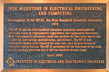
The HP-35 was the epitome of a revolutionary mousetrap. Hand-held four function calculators were already on the market. Few could imagine a machine with scientific calculation capability that would fit in your shirt pocket, but could readily see the use and the need started growing in their mind. Many of us think of themselves as inventors, but what we should be focusing on is innovation; making something that others want, and will buy. Research should support development of the end product. If something new and novel results, then perhaps an invention evolves that could be patented. Many engineers begin a design from the inside, i.e., the hardware, or engine, and then put a body around it. However analyzing the more successful products introduced over the last few decades show they were developed from the outside; the look, touch and feel. During the development of the desktop HP 9100 calculator I was responsible for developing the algorithms to fit the architecture suggested by Tom Osborne. Although the suggested methodology for the algorithms came from Malcolm McMillan I did considerable amount of reading to understand the core calculations many dating back more than 1000 years. Although Wang Laboratories had used similar methods of calculation, my study found prior art dated 1624 that read on their patents. This research enabled the adaption of the transcendental functions through the use of the algorithms to match the needs of the customer within the constraints of the hardware. This proved invaluable during the development of the HP-35, even to the point of tuning the 12 digit constants used to generate the functions to minimize bias in the error to less than 1 count in the 11th decimal place. The choice of Algorithms for the HP-35 received considerable thought. Power series, polynomial expansions, continued fractions, and Chebyshev polynomials were all considered for the transcendental functions. All were too slow because of the number of multiplications and divisions required. The generalized algorithm that best suited the requirements of speed and programming efficiency for the HP-35 was an iterative pseudo-division and pseudo-multiplication method first described in 1624 by Henry Briggs in 'Arithmetica Logarithmica' and later by Volder and Meggitt. This is the same type of algorithm that was used in previous HP desktop calculators. Additionally the investigation during the development of the HP-9100 desktop calculator suggested the use of reverse Polish logic as a cornerstone in the design of the HP-35 affecting every aspect from number of keys to internal logic architecture. Reverse Polish required entering the operator after the operands therefore eliminating parenthesis; requiring less key-strokes as well as simpler hardware. The calculator project started out as just that, a scientific calculator that would fit in Mr. Hewlett's shirt pocket. Prior to the first prototype Hewlett named the calculator the HP-35 after the number of keys. The initial goals set for the design of the HP-35:
What did the HP-35 need to look like? It had to be pocket-sized, that meant light weight and easily held. What keys or buttons would be necessary, how would they all fit within the size limitation? Would users accept prefix and suffix keys? How would the keys be placed for ready access; could accidentally hitting adjacent keys be avoided? Battery life had to be at least several hours before recharging. The display had to be readable at arms length, even in bright sunlight. The industrial design of the HP-35 was unusual not only for Hewlett Packard, but for the electronics industry in general. Usually the mechanical and electrical components of a product are determined before the exterior is designed; the HP-35 took the opposite approach. Since the calculator was to fit in a shirt pocket, size was the overriding constraint on the design. Several other parameters were initially established; the calculator would need three batteries necessary to achieve the desired battery life with a high DC to DC converter efficiency at the estimated semiconductor voltage and current needs. Based on previous HP desktop calculator design the HP-35 would have 35 keys (isn't it apparent that the pocket calculator was named after the design was finished?) and a fifteen digit LED scientific format display with decimal point and signs for both mantissa and exponent. The industrial design began with an investigation of keyboard, packaging, and overall shape concepts. Several basic form factors were studied using sketches and simple three-dimensional models which allowed a good evaluation of the shapes and sizes being considered. From a human-engineering standpoint, the keyboard was the most critical area of the design. The problem was to place thirty-five keys in an area approximately 2-1/2 inches by 4-1/2 inches and retain the ability to operate the keys without striking more than one at a time. It became apparent that the industry standard of 3/4-inch center-to-center key spacing could not be maintained. A successful compromise was to use 11/16-inch center-to-center spacing for the numeric keys, and 1/2-inch spacing for all others. This was made possible by reducing the size of each key, thereby increasing the space between the keys. The keys are divided into groups according to functions. The groups are separated by size, contrast, color, and placement of nomenclature. The numeric keys, which are most frequently used, are larger and have the strongest contrast. They have their nomenclature directly on the keys. The next group of keys according to frequency of use is identified by their blue color. The ENTER key and arithmetic keys are separated within this group by placement of nomenclature on the keys. The less frequently used keys have the least value contrast, and the nomenclature is placed on the panel just above the key. Requirements for the HP-35's keyboard were particularly difficult. The keyboard had to be reliable, inexpensive, and low-profile, and have a good 'feel'. The solution was based on the 'oilcan' or 'cricket' principle, that is, curved metal restrained at the edges can have two stable states. The keys had an over-center or snap feel when they are pressed to provide tactile feedback similar to a child's cricket. This came from special spring contact developed by HP all within 1/8-inch high. The keys had a definite 'fall-away' or 'over-center' tactile feel so that there was no question when electrical contact was made. The external package of the HP-35 was developed from a human-engineering approach, with aesthetic appeal of major importance. The sculptural wedge shape permits the calculator to be comfortably held in the palm of one hand. It also allows the product to slide easily into a pocket. The keyboard and display slope upwards for a better viewing angle in desk-top use. The sculptural sides visually break up the total mass of the package. The top half of the case is highlighted while the bottom half is in shadow. This gives the product the appearance that it is thinner than it actually is. The product appears to be floating when viewed from a normal operating position in desk-top use. The use of textures that complement each other contribute significantly to the overall finesse and appearance. The texture on the case provides a non-slip surface, important when the calculator is being hand-held. Only a general idea of the electronic design was known at this point. Designing and packaging all necessary electrical and mechanical components into the tiny product became a tremendous challenge for electrical, mechanical, and industrial designers alike. The HP-35 couldn't have been developed without an outstanding working relationship between the development laboratory, industrial design, manufacturing, and tooling engineering. Everyone involved in the project shared a common desire to retain the original size and shape, and many innovative engineering concepts resulted. Many of the problems encountered during development could have been easily solved by using more conventional methods, but this would have meant missing the target goals and resulted in a lesser mousetrap. It was apparent early in the HP-35 planning that new display techniques would be required. Existing light-emitting-diode products used too much power and cost too much. A magnified five-digit cluster saving both power and cost with an integral plastic spherical lens for each digit was developed by HP. LED's are more efficient if they are pulsed at a low duty cycle rather than driven by a dc source. In the HP-35, energy is stored in inductors and dumped into the light-emitting diodes. This drive technique allowed a high degree of multiplexing; the digits were scanned one at a time, one segment at a time. Extensive reliability testing showed insignificant change in intensity after years of high current pulsing at duty cycles of one-tenth of a per-cent. The readability of the display, even in bright sunlight was so important that the individual segments were tuned by adding a slight serif to the left edge of the top and bottom bars and trimming. Each segment was also modified to have comparable perimeter to area ratios to provide uniform visible intensity. Based on experience with the full ten digit display on the Hewlett Packard desktop calculators the display of the HP-35 was set up similarly consisting of 15 seven-segment-plus decimal-point light-emitting-diode (LED) numerals. Answers between 1010 and 10-2 were always displayed as floating-point numbers with the decimal point properly located and the exponent field blank. The display was left justified with trailing zeros suppressed. Outside this range the HP-35 displayed the answer in scientific notation with the decimal point to the right of the first significant digit and the proper power of 10 showing at the far right of the display. To make the display more readable, a separate digit position was provided for the decimal point. The HP-35 contained five MOS/LSI (metal-oxide, semiconductor/large-scale-integration at the time) circuits: three read-only-memories (ROMs), an arithmetic and register circuit (A&R), and a control and timing circuit (C&T). The logic design was done by France Rode` and Chung Tung of HP Laboratories and the circuits were developed and manufactured by two outside vendors. Three custom bipolar circuits were also designed by HP Laboratories and manufactured by HP's Santa Clara Division; a two-phase clock driver, an LED anode driver/clock generator, and an LED cathode driver. The HP-35 was assembled on two printed circuit boards. The upper board contains the display and drivers and the keyboard. The lower and smaller board has all the MOS logic, the clock driver, and the power supply. The battery selection and design of the power supply were not trivial; a three battery stack was chosen to increase the single transistor DC to DC converter efficiency of greater than 80% to obtain the four hour battery life objective. Chu Yen PhD of HP Laboratories obtained this super efficiency even while supplying the various voltages (+7.5v, +6v, and -12 v. necessary to power the MOS and Bipolar circuits used in the calculator. Similar design concepts were used for the recharger/AC adapter. The calculator data was organized as digit-serial/bit-serial race track architecture. This organization minimized the number of connections on each circuit and between circuits, thereby saving area and cost and improving reliability. Each word consists of 14 binary-coded-decimal digits, or 56 bits long. Ten of the 14 digits are allocated to the mantissa, one to the mantissa sign, two to the exponent, and one to the exponent sign. Three main bus lines connect the MOS circuits. One carries a word synchronization signal (SYNC) generated by a 56-state counter on the control and timing chip. On another bus, instructions (Is) are transmitted serially from the ROMs to the control and timing chip or to the arithmetic and register chip. The third bus signal, called word select (WS), is a gating signal generated on the C&T chip or by the ROMs; it enables the arithmetic unit for a portion of a word time, thereby allowing operations on only part of a number, such as the mantissa or the exponent. The control and timing (C&T) circuit performs the major non-arithmetic, or housekeeping functions in the calculator. These include interrogating the keyboard, keeping track of the status of the system, synchronizing the system, and modifying instruction addresses. The keyboard is arranged as a five-column, eight-row matrix. It is scanned continuously by the C&T chip. When contact is made between a row and a column by pressing a key, a code corresponding to that row and column is transmitted to the read-only memory (ROM). This code is the starting address of a program in ROM to service that key. Key bounce and lockout are handled by programmed delays. In all digital systems, status bits or flags are used to keep track of past events. In the HP-35 there are twelve status bits, all located on the C&T chip. They can be set, reset, or interrogated by microinstructions. ROM addresses are updated on the C&T chip and sent serially to the ROMs. During execution of a branch instruction, the appropriate signal -- arithmetic carry or status bit -- is tested to determine whether the incremented address or the branch address should be selected next. One of the most significant features of the serial organization was the ability to operate on just a single digit or a group of digits of a number as it flows bit-serially through the arithmetic unit. This unique design organization minimized the architecture allowing the HP-35 even to be built at that time yet enabled the elementary add routines to be easily put together to form extremely powerful subroutines that could execute completely in less than one second. Based on the race track analogy imagine the grandstand as only seeing one horse or bit passing by at a time. Then after each four horses or bits the calculations for that digit are completed. The word-select signal corresponds to the number of digits or groups of horses in sequence or time slot being operated upon for that total word cycle. Preprogrammed mathematical routines were stored in three ROM chips, each of which contains 256 instructions of 10 bits each. Only one of the three ROM chips is used at any time, the unselected ROMs were turned off. The arithmetic and register circuit executes instruction bit-serially. Most arithmetic instructions must be enabled by the word-select signal. Data to be displayed is sent to the LED anode drivers and carry line transfers carry information back to the C&T chip. The BCD output is bidirectional and can move digits into and out of the A&R chip. The A&R circuit is divided into five areas: instruction storage and decoding circuits, a timing circuit, seven 56-bit registers, an adder-subtractor, and a display decoder. Three of the registers are working registers. One of these and three of the remaining four registers form the four-register stack. The seventh register is an independent register for constant storage. There are numerous interconnections between registers to allow for such instructions as exchange, transfer, rotate stack, and so on. An advantage of the bit-serial structure is that interconnections require only one gate per line. Transfers into or out of the stack or the constant register are always whole-word transfers. All other arithmetic instructions are controlled by the word-select signal. Thus it's possible to interchange only the exponent fields of two registers, or to add any two corresponding digits of two registers. The adder-subtractor computes the sum or difference of two decimal numbers. It has two data inputs, storage for carry or borrow, and sum and carry/borrow outputs. For the first three clock times, the addition is strictly binary. At the fourth clock time the binary sum is checked, and if the answer is more than 1001 (nine), then the sum is corrected to decimal by adding 0110 (six). The result is then entered into the last four bits of the receiving register and the carry is stored. A similar correction is done for subtraction. Carry information is always transmitted, but is recorded by the control and timing chip only at the last bit time of the word-select signal. In designing elaborate integrated circuits like the C&T, A&R, and ROM chips, two questions that have to be answered at the very beginning are: How is the design to be checked? and How is the final integrated circuit to be tested? The first question has two answers. One is to build a breadboard and compare its operation with the desired operation, or do a computer simulation of the circuit. When the MOS circuits (C&T, A&R, and ROMs) for the HP-35 were being designed, the computer simulation approach was chosen over a small-scale transistor/transistor logic (TTL) or MOS breadboard. It was felt that the hardware breadboard wouldn't be an exact model of the final circuits anyway, and two or three months of development time could be saved by computer simulation because people could work in parallel rather than serially on a breadboard. A general-purpose simulation program had just been developed by Jim Duley of HP Laboratories. This was used to check out each gate, each circuit, each chip, and finally all the chips together. Each MOS circuit is designed as a network of gates and delay elements. For each gate output an algebraic equation was written as function of the inputs to the gate. This produced a large set of algebraic equations to be evaluated every clock time. A printout was available so the operation of any of the gates or delay outputs could be observed, as if with an oscilloscope probe. In this respect the computer simulation was much better than a hardware breadboard. Because of the large number of equations to be evaluated each clock time the general-purpose simulation program was too slow to use for evaluating the algorithms implemented in the ROMs. For this a higher-level simulation was used, so only the input/output functions of each subsystem had to be specified. This was fast enough that all the algorithms could be checked, even the transcendental functions. If anything went wrong it was always possible to stop the program and step through it until the trouble was found. Correcting a problem was a simple matter of changing a punched card or two, an advantage a hardware bread board doesn't have. The simulation approach proved very successful. It saved a lot of time not only in logic design, but also in generating the test patterns to be used for testing the final integrated circuits. After a simulation is running successfully a pattern for each input is specified such that virtually every circuit element will be exercised. By running the program and recording all the inputs and outputs a complete test pattern is generated, ready for final test of the integrated circuit. An estimate of program execution times was made, and it became apparent that, by using a bit-serial data word structure, circuit economies could be achieved without exceeding a one-second computation time for any function. Furthermore, the instruction address and instruction word could be bit-serial, too. The complexity of the algorithms made multilevel programming a necessity. This meant the calculator had to have subroutine capability, as well as special flags to indicate the status and separations of various programs. In the HP-35, interrogation and branching on flag bits or on arithmetic carry or borrow are done by a separate instruction instead of having this capability contained as part of each instruction. This affords a great reduction in instruction word length with only a slight decrease in speed. To generate a transcendental function such as Arc-Hyperbolic-Tan required several levels of subroutines. However subroutine calls were made by setting flags, so flow charting and control was paramount. Chris Clare later documented this as Algorithmic State Machine (ASM) methodology. Even the simple Sine or Cosine used the Tangent routine, and then calculated the Sine from trigonometric identities. These arduous manipulations were necessary to minimize the number of unique programs and program steps to limit the HP 35 to 750 words of read-only-memory three chips). The arithmetic instruction set was designed specifically for a decimal transcendental-function calculator. The basic arithmetic operations are performed by a 10's complement adder-subtractor which has data paths to three of the registers that are used as working storage. Partial word designators (word select) are part of the instruction word to allow operating on only part of a number for example, the mantissa or the exponent field. Determination of the accuracy of the HP-35 is as complex as its algorithms. The calculator has internal round-off in the 11th place. In add, subtract, multiply, divide, and square root calculations the accuracy is 1/2 count in the 10th digit. In calculating the transcendental functions many of these elementary calculations are performed with the round-off error accumulating. In the sine computation there is a divide, a multiply, and a subtract in the pre-scale operation, and there are two divides, a multiply, an addition, and a square root in the post-computation. Round-off errors in these calculations must be added to the error of the basic algorithm to get the total error. Accuracy and resolution are sometimes in conflict: for example, the subtraction of .9999999999 from 1.0 yields only one digit of significance. This becomes very important, for example, in computations of the cosines of angles very close to 90°. The cosine of 89.9° would be determined more accurately by finding the sine of 0.1°. Similarly, the sine of 1010 wastes all ten digits of significance in specifying the input angle, because all integer circles will be discarded. The HP 35 was the dream development. The timing was a perfect storm of high density silicon technology just emerging; I had the algorithms in my back pocket from the 9100 application and the customer demand for on-the-go calculations. The physical appearance had been on the drawing board for months, commissioned by Hewlett. When I saw a racetrack architecture designed in PMOS, I knew it was suitable. Fairchild Semiconductor was touting it for fixed point calculator four-function applications. Although not quite a perfect fit for the algorithms I needed I could make it work. When Fairchild decided not to tweak the design to manufacture for HP, I sold Tom Whitney that we could make it ourselves farming the redesign out to AMI and Mostek. Tom convinced Paul Stoft and ran interference of the project all the way. I was in Seventh Heaven to now design my own instruction set, really a reduced-instruction-set (RISC) as there wasn't enough silicon in 1970 on a chip to have anymore than necessary. Each instruction had to call some kind of combinatorial logic of operation, so what would be the bare essentials. I hated the key-down instruction because it was only used once per function. I originally had two instructions for both conditional branch after an operation that could carry or change a flag and unconditional branch. Since these added directly to the word width of the ROM, I decided to use only the conditional branch instruction ensuring that by default I would never use it following a condition setting operation. This reduced the ROM size by 10%, in hind-sight, what in-sight? It's well known that when we went to Hewlett and told him we could do it, he covered his bet by soliciting SRI to do a market study. He held back the development cost of $1M but we used lab working money to cover it. Much of the physical design such as appearance and feel of the keyboard had been in development for some time, not a trivial matter. Even after the HP-35 was in production Bill Hewlett wasn't confident it would be successful. One time at lunch I mentioned to him that we had a Request-for-Quotation from GE for 10,000 units. He said that there must be a mistake, why would they want that many? I replied that maybe they were buying one for each of their engineers. Bill responded by saying they should just buy a few and let their engineers borrow from one another. Dietzgen, the slide rule company folded in about one year after the pocket scientific calculator introduction. In schools throughout the world the question was asked, could they bring the HP-35 to class? It caused a dilemma amongst many teachers, do they let those that could afford the $395 bring them to class; how about tests? Soon many courses required that you buy one as now the instructor could design real problems that didn't have to result in whole numbers. The world was changed forever.
David S. Cochran
June 2010 |
This site has no commercial objective. Nothing is for sale here.
HP Memory Project is not associated with the Hewlett-Packard Company.
The Hewlett-Packard name, HP, the HP logos, the HP model numbers are trademarks of the Hewlett-Packard Company.
Substantial material from various HP publications appears on the site by permission of the Hewlett-Packard Company.