Evolution of Digital Voltmeters
during the 1960 to 1980 Period


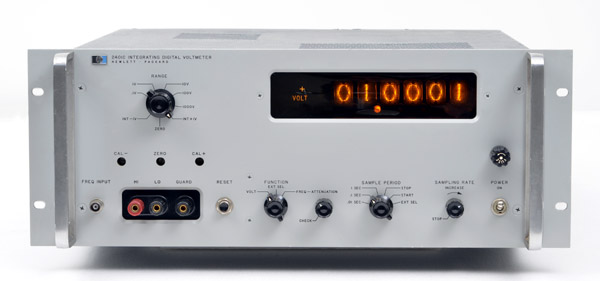 |
| The HP 2401C Integrating Digital Voltmeter |
Digital voltmeter was a very early addition to the HP catalog. As soon as 1959, the HP 405AR was introduced. It was itself an evolution of the illustrious DY-2401 Integrating Digital Voltmeter, certainly Dymec's single most valuable product, in terms of both dollar-volume and contribution to the measurement art. The DYMEC Company was formed in 1956, and in 1959, soon after HP became a publically-traded company, DYMEC which was owned jointly by its own and HP employees, and by the Hewlett-Packard Company, became an HP division.
The product lines designed and manufactured by DYMEC were another important complement to the HP product lines of the time. The DY-2401 digital voltmeter was one of them, but data logging systems and some specialized microwave products were significant developments. DYMEC was assigned to the early design of the HP 2116 digital computer, launching HP into the prominence in computers that it enjoys today, many decades later.
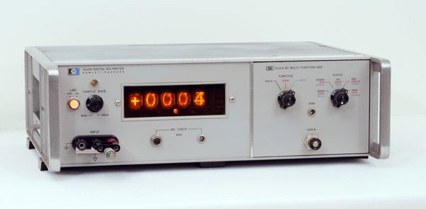 |
| The HP 3440A with 3444A DC Multi-Function Unit |
As often happens in measurement developments, the first product released, as in the HP 405 digital voltmeter, while successful in its own right, revealed areas for improvement, which were combined to yield the super successful HP 3440A. And you won't find any better information about the design of the 3440 than in Dave Cochran's story. In his early years at HP, Dave was the one to accept the job of developing the follow on to the 405B digital voltmeter. Some years later, Dave Cochran will become the legendary father of the HP-35 scientific calculator algorithm. The HP 3440 chapter inside Dave Cochran's story is here, and the full story here on this website. It's a must read. (use your browser back-button to come back here).
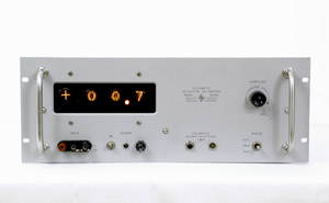 |
The HP 405AR |
The HP 3440A became an extremely successful product for HP. In fact, it became one of HP's top-selling products during the early 1960s. By the end of the 1960s, the 3440 was still a successful product, a small product line in itself, thank to its modular design. The 1970 datasheet below gives more detail.
The HP 405AR, while introduced before the 1960s, was a pioneering effort by HP to broaden its legendary line of analog meters. It's "clunky" appearance, available only with the rack-mount ears, was not appealing on a test bench. But since it was introduced along with the HP 561 digital printer, it was often rack mounted as part of a data logging system, an early breakthrough in "automatic" measurements.
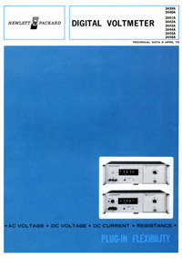 |
Cover of the 3440A Tech. Data - Apr. 1970 |
Click on the link below for a PDF of the HP 3439A/3440A Digital Voltmeter Technical Data Sheet. It was published in April 1970.
HP 3439A/3440A Digital Voltmeter Technical Data - PDF File (1.3 Mb)
Early digital voltmeters discussed above, HP 405A and HP 3440A, used a null balance or potentiometric system to convert the unknown voltage into a digital presentation of that voltage. These instruments, however, were relatively slow-responding and expensive. In a step towards achieving speed and accuracy at reduced cost, Hewlett-Packard in 1959 developed a digital voltmeter which depends on measuring the time required for an internal linear voltage ramp to pass from a reference level to a level equal to the unknown DC input voltage.
This time interval, which is proportional to the input voltage, is measured by a built-in electronic counter to obtain a digital indication of the input voltage. The basic simplicity of the ramp technique has resulted in reliable and economical voltmeters with typical accuracies of better than 0.05%.
Improvements with time have increased the ability of the digital voltmeter to cope with a variety of measurement problems. A serious problem has been the effects of superimposed noise on the accuracy of the measurement, since noise yields a slightly different number with each scan. To permit successful and accurate readings in the presence of noise, a large amount of filtering was usually added at the input, but this limited measuring speed by slowing response.
The voltage-to-frequency conversion technique also lends itself to electrostatic guarding of the input circuits. Guarding greatly reduces errors caused by common-mode signals, providing a common-mode noise rejection of 160dB at dc and more than 120 dB up to 60 c/s. Typical accuracies which can be obtained with digital voltmeters of the purely integrating type are 0.01%.
In 1965, The potentiometric or null-balance technique, was still the most accurate method of comparing an unknown voltage to a reference. The next innovation was to combine the accuracy of the potentiometric technique with the freedom from the effects of noise that the voltage-to-frequency conversion technique can provide. This was done in the HP 3460A.
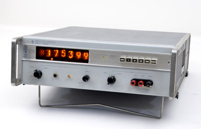 |
The HP 3460A |
The method used to combine the potentiometric technique with voltage-to-frequency conversion in the HP 3460A permits an accuracy of 0.005% at a maximum reading rate of 15 readings per second.
The Model 3460A was designed for use both as a precision laboratory voltmeter and as a system-oriented analog-to-digital converter. It has four voltage ranges, from 1 V to 1000 V full-scale in steps of 10x, with 5-digit (10 microvolt) resolution.
A simplified block diagram of the 3440A is shown below. The voltage-to-frequency converter transforms a voltage at its input to a proportional pulse repetition rate at its output. The reversible counter totalizes the pulses during a fixed period of time. The total count thus is proportional to the average value of the input voltage that existed during the totalizing period. During the first sample period, the output of the voltage-to-frequency converter is counted for 1/60 second to derive an initial measure of the input voltage. This information is then transferred to the digital-to-analog converter without affecting the stored count.
The digital-to-analog converter output voltage, being proportional to the stored count, tends to null the input voltage (an attenuator is inserted automatically on the 10, 100, and 1000-V ranges). During the second sample period, which may be either 1/60 or 1/10 second, the voltage-to-frequency converter measures the residual difference voltage. Since the difference may be either positive or negative, logic circuitry senses whether counts from the voltage-to-frequency converter are to be added to or taken away from the previous stored count.
At the end of the second sample period, the final count in the reversible counter is transferred to front panel indicators for display. A print command is also issued to permit recording of the data by external equipment.
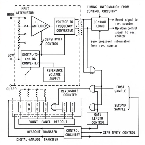 |
| The HP 3460A Block Diagram - From the Hewlett Packard Journal, August 1965. Courtesy of the Hewlett Packard Company |
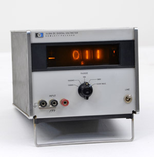 |
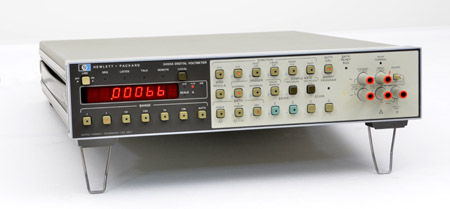
The HP 3430A |
"3 Digit DVM at the price of analog voltmeters"
The first HP low-cost Digital Voltmeter was introduced in a short-form catalog specially edited for the 1966 WESCON exhibition. Its price at introduction was $595; to be compared to the $4,000 for a 3460 at the same time.
The 3440A is able to make full-scale DC voltage measurement from ±100.0 mV to ± 1000 V with up to 60% overranging. To save costly frequent calibration, the 3430A maintains its ± (0.1% of reading +0.1% of range) accuracy for 90 days.
The HP 3440A has a 3-digit display with 60% overranging indicated by a 4 th digit. The imput inpedance is 10 MΩ.
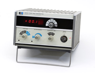 |
The HP 3403A |
By the early 1970s, broadband measurements of true RMS voltage used to be costly or inaccurate or both.
In 1972 the first project which introduced the HP 3403A and 3403B True-RMS Voltmeters featured a combination of capabilities previously unobtainable. The 100-MHz bandwidth target was 5 times greater than even the widest band analog types (excluding, of course, the RF-only voltmeters). Midband accuracy was to exceed that realizable by anything other than very costly true-rms digital types.
As developed, the 3403A in addition to measuring true RMS AC also measured directly the RMS value of a waveform containing both AC and DC. it also measured the DC component alone; the 3403B measures true RMS AC only. A dB option allows the choice of readings either in volts or in dB; the dB reference is adjustable, and found acceptance with engineers working towards the radio frequencies. Autoranging is optionally available, as are systems features (remote programming and control, and BCD outputs, isolated or not). The 3403A input connector can be floated, a common need for DC or low-frequency measurements. Input impedance is high, so any of the usual voltmeter measurements may be made.
Both the 3403A and 3403B had a very short commercial life. Introduced in the 1972 catalog, they both disappeared in the 1973 catalog in favor of a new Model: the HP 3403C which combined the specifications of its two predecessors.
Main specifications of the 3403C were the following: Full range display: 10.00 mV (ac only); 100.0 mV, 1.000 V, 10.00 V, 100.0 V, 1000 V. Functions: DC, AC, AC + DC. AC Frequency range: 2 Hz to 100 MHz at 10 secondes response time, and 25 Hz to 100 MHz at 1 second response time. Calibrated dB reference: 0 dB = 1.000 V.
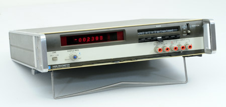 |
The HP 3490A |
The HP 3490A is a 5-digit, autoranging, fully-guarded, integrating Multimeter with self-test capability. The most sensitive DC range is 100 mV full scale, giving the instrument 1 µV resolution. Accuracy is better than 0.01% of reading and the voltmeter overranges to 20% above full scale on all ranges except the 1000-volt range. The input is fully protected against excessive voltages, with a standing 1000 volt input protection on all ranges including the 100 millivolt range. The instrument can make five readings per second and when autoranging to another voltage range, it switches at a five-per-second rate.
The Multimeter also measures resistance by the four-wire technique in 6 ranges from 100 Ω full scale to 10 MΩ, and it measures AC voltages in four full-scale ranges from 1 to 1000 volts. Frequency range is 20 Hz to 100 kHz on the 100 and 1000 V ranges and 20 Hz to 250 kHz on the 1 and 10 V ranges.
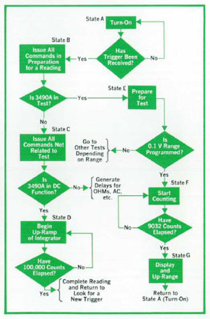 |
Typical flow chart used in algorithmic state machine logic of the HP 3490A Mulitimeter |
The 3490A self-test capability was achieved by an algorithmic state machine logic design. Low cost microprocessors were not yet available on the consumer market in 1972. But many years before, the design of process controller based on a set of procedures known as Algorithmic State Machine Logic design, had been developed at the HP Laboratories in Palo Alto, and integrated in a variety of measuring instruments.
In the 3490A, the quickest test is one that causes the instrument to read its own internal positive reference voltage using the negative reference voltage as the measurement reference. The measurement automatically repeats with the roles of the reference voltages interchanged. This gives a quick indication that the voltmeter is indeed ready to make measurements. This test also discloses any voltage level difference between the reference sources.
Another internal test is a series of 10 tests that the voltmeter steps through automatically. When this test is initiated, the instrument autoranges one step for each reading, up through all ranges and then back down again. During each step, the data counters are permitted to count for periods of time that differ for each range. The operator can compare the resulting readings with a list on a pull-out instruction card attached to the underside of the instrument. If the series of readings agree with the card, the operator can be sure that the display, ranging and counting circuits, and at least 70% of the logic, are all functioning correctly.
Other tests, more useful for troubleshooting and calibration, check the calibrations of the input attenuator and amplifier and check for amplifier offsets in various parts of the instrument. The tests (1 and 10 V), thereby reducing the number of verification standards needed to support the instrument.
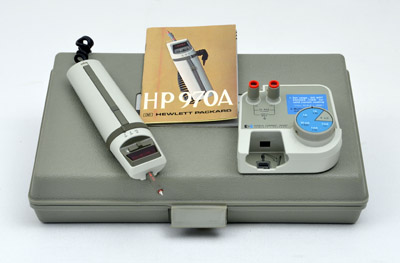 |
The HP 970A with its original carrying case, and 97002A Accessory Current Shunt |
This could be seen as a curiosity today, but in 1973 a digital hand-held multimeter was a new concept in instrument utility.
The Model 970A Digital Multimeter was designed for convenient hand-held operation. The user needed only to select the desired function and press the power switch to take a reading. The instrument automatically selects the right measurement range.
The HP 970A is a battery-powered 3 1/2 digit Probe Multimeter that is completely self-contained and can be held and operated in one hand. The instrument has autoranging, autopolarity, and autozero, which means the user need only set the function switch and depress the power bar to get an accurate reading.
In addition, the probe tip can be pivoted into three detented positions: straight, tilted at 30, and tilted at 60°. The tip can be folded back so that the Probe can be carried in a pocket or the belt-carrying case provided with the instrument.
 |
Slide switch adjacent to the display inverts the numerals so readings can be taken with the probe upside down |
But the 970A is first of all a real instrument. It is a true digital multimeter with three digits of readout plus a "1" for 10% overranging. The most sensitive range for both AC and DC measurements is 100 mV full scale with 0.1 mV resolution. Although the input is protected up to 1000 V, for safety reasons the maximum input voltage is specified at 500 V. The accuracy of readings is better than 1% for DC voltages and between 2 and 5% for AC.
The input impedance is 10 megohms paralleled by less than 30 pF. The ac frequency range is up to 3500 Hz, wide enough for power line and most voice-channel measurements.
As an ohmmeter, the multimeter has fullscale ranges from 1 to 10,000 kilohms with a resolution of 1 ohm on the lowest range. The accuracy of ohms readings is better than 2%. In all functions, the instrument displays a reading in less than 2 seconds after the switch is pressed (to speed this up, it starts at mid-range and then ranges in the appropriate direction). In continuous operation, it makes 3 readings per second.
The Ni-Cad batteries that power the instrument can operate continuously for a minimum of 2 1/2 hours before needing recharge, but by pressing the switch only when a reading needs to be taken, the user can make at least 2000 readings on one charge.
On a technical point of view the Probe Multimeter is an integrating digital voltmeter that employs the widely-used dual-slope technique to derive a digital display from a DC voltage. As much of the circuitry as possible was put on one monolithic integrated circuit, a 150 x 170 mil chip (3.9 x 4.3 mm) made by an N-MOS process developed for the 4096-bit ROM's used in HP calculators. This chip (left part on picture below) includes the counters, buffer storage, code conversion for the display, display scanner, autorange circuits, several ROM's that store the programs needed to operate the multimeter (approximately 3500 bits are stored in ROM), and most of the analog switching.
As much as possible of the remaining circuitry was put on a 28 x 38 mm thin-film hybrid circuit (right part on picture below). This includes six operational amplifiers (three chips, each with two op amps), the comparator, one chip with the two input FET's, the bipolar current amplifier that drives the display, four diode chips (rectifiers and protection diodes), capacitor chips, high-value resistor chips, and tantalum-nitride thin-film resistors.
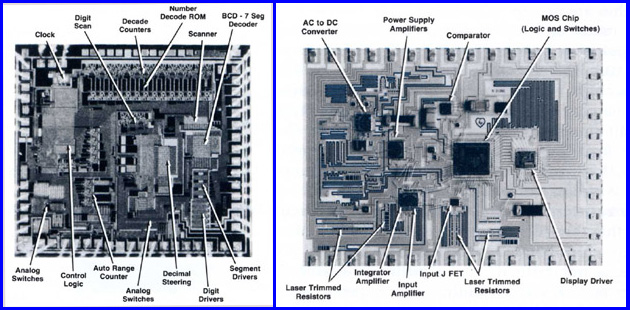 |
| Monolithic integrated circuit (left), and thin-film hybrid circuit (right) specifically designed for the HP 970A See text above for detail |
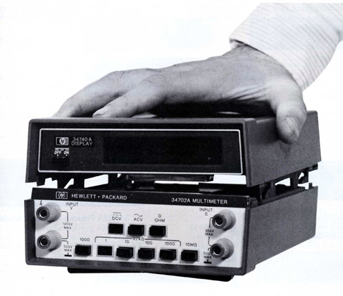 |
The Model 3470 Measurement System consists of display section and various signal-conditioning sections plus battery and BCD output sections which fit together in combinations to suit differing users needs. The 3470 series has sections that plug together to form a complete instrument in the same way as the Hewlett-Packard 5300 series counters. The top section has a ±1 volt A-to-D converter, a 4 1/2-digit display, power supplies for the whole instrument, and necessary control circuits. The bottom section has signal-conditioning circuits needed to convert the measured quantity into a dc voltage within the ±1-volt full-scale range, which serves as input to the top section.
A center section can be placed between the top and bottom sections to give additional capabilities. Initially these include a BCD module (Model 34721A) that converts the readout into binary-coded decimal format for driving printers or other data processing equipment, and a rechargeable battery module (Model 34720A) that provides more than six hours of line-independent operation (the instrument uses only 5 watts).
 |
The HP 34740A Display and 34703A Multimeter Module |
At its introduction in the 1973 catalog, the HP 3470 Series immediately offered a large choice of interchangeable modules to match the display/mainframe, and functional module to a wide range of measurement capability.
The 34740A four-digit display (pictured on the left), and 34750A five-digit display, lock onto any center section or voltmeter module to form a complete DVM.
There were 3 bottom signal-conditioning sections:
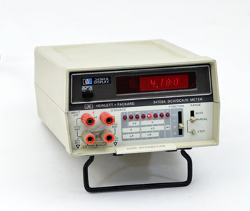
The 34701A, low-cost DC voltmeter provides four ranges of DC from 1 V to 1 kV full scale.
The 34702A Multimeter plug-on provides four ranges of DC and AC (1 V to 1 kV F.S.) plus 6 ranges of resistance measurement (from 100 Ω to 10 M Ω). The AC function covers 45 Hz to 100 kHz.
The 34703A autoranging plug-on (picture above) provides 6 ranges of DC volts (10 mV to 1 kV F.S.), 6 ranges of DC current (±1 µA to ±100 mA F.S.), and 8 resistance ranges (from 1 Ω to 10 M Ω).
There were also three center modules: The 34721A BCD module provides nonisolated BCD output for operation with printers and other devices. The 34702A battery module makes the 3470 into a portable DVM with six hours of continuous operation. And the 34722A preamplifier module provides added sensitivity to the 34701A and 34702A modules.
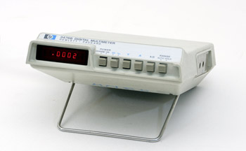 |
The HP 3476A |
The 3476A, introduced in the 1977 catalog was, first of all, an Economical 3 1/2-Digit Multimeter.
The most striking feature of this compact instrument is its unorthodox shape, a shape that evolved from human factor considerations. One might mistake it for a consumer product. The thin, flat enclosure allows the instrument to be carried conveniently in a brief case or in a tool box. The upward slope on the forward edge of the top surface provides a convenient finger rest to prevent the instrument from sliding away when the pushbuttons are pressed. It also provides a handy grip for picking up the instrument. The "roof" over the display shields the LED display from direct light, enhancing its readability. The rim running below and up at each end of the row of pushbuttons protects the buttons from impact should the highly-portable instrument be dropped accidentally.
The 3 1/2-digit instrument measures DC and AC volts, DC and AC current, and resistance. It has autoranging and autopolarity selection but it also has a range-hold function that retains a range regardless of input changes. Full-scale ranges are from ±0.110V to ±1000V DC and AC, ±0.110 and ±1.10 A DC and AC, and 1.10 kΩ to 11,000 kΩ.
 |
The HP 3455A |
By the end of the 1970s, a new generation of test instruments that used microprocessor-based logic for internal control was emerging. This trend dramatically enhanced functional and performance design.
The microprocessor can give increased measurement capability while at the same time making the instrument easier to operate, and it can also make the instrument easier to calibrate and maintain.
That is the story behind the Model 3455A Digital Voltmeter. An internal microprocessor gives this voltmeter the capability of processing its own readings, thus making it possible to display temperature, for example, when measuring the corresponding voltage output of a thermocouple, or read the percentage deviation of a reading with respect to an earlier reading. Easier operation is also obtained, in this case ease of interfacing it to the HP interface bus for systems use.
The Model 3455A Voltmeter measures DC volts, AC volts, and Ohms. Under programmed control, it can make 24 dc-voltage readings per second with 5 1/2 digit resolution and with 60 dB of normal-mode and 160 dB of common-mode noise rejection (at 60 Hz). It also has a slower-reading high-resolution mode that displays results with 6 1/2 digits (except on AC voltages and on the 0.1 DCV and 100 Ω ranges). Basic accuracy for DC volts and ohms is 0.005%. AC voltage readings are normally made at a rate of 1.3/second but a FAST AC mode enables 13 readings per second (under programmed control) on signals having frequencies above 300 Hz. The true-rms converter has a frequency range of 30 Hz to 1 MHz, a crest factor of 7:1, and AC + DC capability. An optional lower-cost averaging AC converter has a frequency range of 30 Hz to 250 kHz.
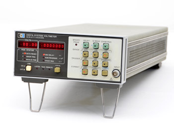 |
The HP 3437A |
Waveform characteristics as well as DC levels can be determined by this fast sample-and-hold voltmeter when teamed with a calculator or computer. Optimized for systems use, it has a programmable trigger delay that gives it unusual capabilities.
The Model 3437A evolved from the observation that the majority of measurements made by a systems voltmeter require accuracies no better than 0.5%. A resolution of 3 1/2 digits is therefore sufficient. Coupled with a successive-approximation type analog-to-digital converter and fast-responding input circuits, this allows the new voltmeter to settle in 1.5 /us within 3 mV of a 1-volt step input, and to output the voltage magnitude and sign less than 200 µs later.
Of what use is this speed? First of all, it enables a data acquisition system to make many measurements practically simultaneously, when measured on the time scale of most processes. This would be useful for examining changing temperature profiles, for example, during studies of heat flow. This measurement speed can have a significant effect on systems economics, particularly for production test systems where the time taken to run through a test sequence is a significant part of the time taken to handle the device under test. Another example concerns measurements of DC voltages contaminated with AC line interference. If two samples of this voltage, separated by a time equivalent to 180° of the interfering AC frequency, are taken and averaged, the interfering frequency and all its odd harmonics can be rejected.
The 3437A has three floating input ranges: ±100 mV, ±1V, and ±10V with a maximum display of ±1998 (and appropriately positioned decimal point). Of the two numeric displays, one indicates the measured voltage. The other gives the trigger delay, or the number of readings to be taken in a burst.
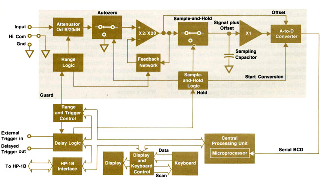 |
| Simplified block diagram of Model 3437 A System Voltmeter. From the Hewlett Packard Journal, February 1977. Courtesy of the Hewlett Packard Company |

|
Use your scrollwheel to zoom in/out |
|
|
|
Top-Inside View of the HP 3455A Digital Voltmeter |
