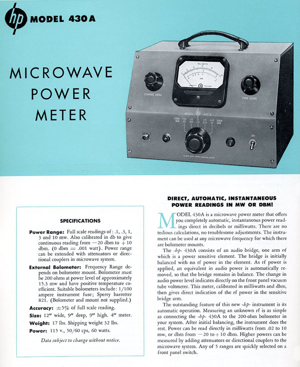
1950 First Microwave Power Meter
The 430A, first HP Power Meter was introduced in 1948 and appeared in the 1950 catalog page 50. Its description occupied the full edition of the May 1950 Hewlett-Packard Journal. This first generation of power meter used a self-balancing bridge and an audio voltmeter.
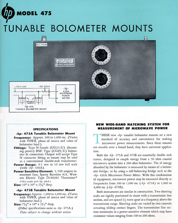
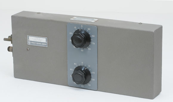
An external bolometer was connected to one arm of the bridge as a non-linear resistor. Two models of bolometer mount were available for this first product: The 475A, was useable from 300 to 1000 Megacycles, and the 475B from 1000 to 4000 Mc.
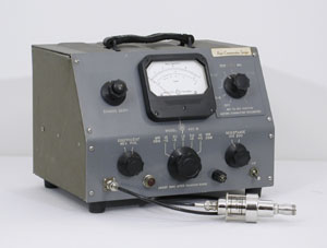 |
The HP 430B Power Meter
And 476A Broadband Bolometer Mount
|
Wide Band No Tuning
A great improvement in ease of use was introduced in 1951 with the 430B Power Meter and the 476A first broadband bolometer mount.
The 476A covered in one range from 10 Mc to 1000 Mc without any tuning. The 430B, 476A combination gave for the first time a tool to measure power level from 0.1 to 10 milliwatts in the RF, VHF and UHF ranges with direct 50 Ohms load match to the signal source under test.
The same Hewlett Packard Journal, dated March-April 1951, also introduced a complete set of waveguide bolometer mounts to extend the 430B upper frequency coverage up to the 12,400 Megacycles microwave region.
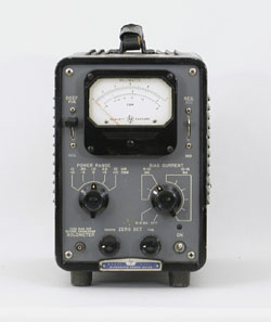 |
The HP 430C Microwave Power Meter |
The 1955 430C Power Meter
The 430C introduced in the March 1955 Hewlett Packard Journal didn't widely improve the power meter performance but it was a necessary adjustment of the compatibility of the measurement device with the many new type of power probes found not only in the Hewlett Packard catalog but also from some other microwave components providers like SPERRY or NARDA.
Many new measuring heads could be found on the market in 1955. They could be bolometers or thermistors, positive or negative temperature coefficient and may have had 100 or 200 Ohms operating resistance. The 430C offered a way to match all these various characteristics in a single instrument with full scale reading of 0.1 to 10 milliwatts also calibrated in dBm to give continuous reading from -20 to +10 dBm.
Rather than in the power meter performance, the major 1955 improvement was in the 477A coaxial thermistor mount which covered the frequency range of 10 mc to 10 kmc. This made the combination of the 430C and 477A the first occurrence of an instrument capable of measuring the power level of a signal from RF to Microwave without any connector change or any manual tuning.
The result was a considerable gain of time in production testing and calibration, and a considerable reduction of measurement errors.
Measuring Higher Power
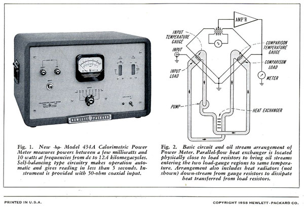
The 434A Calorimetric Power Meter was introduced in the August, 1958 Hewlett-Packard Journal as "An Automatic DC to X-Band Power Meter for the Medium Power Range".
To measure high-frequency power in the range above the low milliwatt region where direct bolometric methods reach a limit, it has been usual practice to retain the basic bolometric method but to reduce the power actually measured by a known amount with attenuators and directional couplers. Although this approach provides useful information, a direct method is fundamentally more desirable, since it would avoid the inconvenience of cascading several components into a measuring setup and would also avoid the errors that additional components introduce into the measurement.
Such a direct approach is achieved by a new power meter that automatically measures average power in the range from 10 milliwatts to 10 watts. The instrument is useful to at least 12 kilomegacycles and is also capable of use down to dc if desired. It can be used to measure any of the common forms of power such as ordinary amplitude-modulated, pulsed ac, pulsed video, and dc. In distinction to methods where the rf load is built into a special external mount, the new instrument contains an internal 50-ohm load which acts as the rf termination and is provided with a type N coaxial connector on the panel.
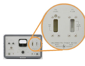 |
Detail of HP 434A Front Panel
Showing OIL LEVEL and OIL FLOW Indicators
|
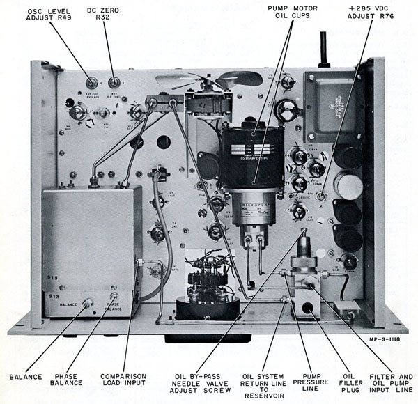
The Plumber's Nightmare
A very short and clear explanation of the 434A Calorimeter principle of operation is given by John Minck in his "Inside HP narrative"
The HP 434A was a miniature plumbers' nightmare. To dissipate the incoming 10 watt signal, a flowing silicone oil stream was envisioned. Further, to provide an insensitivity to temperature changes and outside environments, a balanced arrangement was used. The same oil stream flowed past the microwave resistor that handled dc to 12.4 GHz signals and proceeded to a temperature sensor. Then after a heat exchanger it went on to another termination resistor and temperature sensor, that accepted only a balancing dc power. By supplying the dc power in proportion to the unbalance in two temp-sensors in a single oil path, a measurement of the dc power equaled the microwave power.
It worked great and the dc substitution made it quite accurate. It had little drift, which was a considerable problem on the previous HP 430/478 power bridge technology. The idea of measuring medium power directly without resort to couplers or pads appealed to engineers. The product was a commercial success.